One of the most significant single-chip radio transceivers is the NRF24L01 pinout. We’ll explore the nrf24L01 pinout, features, and how to use the NRF24L01 module in serial communication.
Contents
- 1 What is the NRF24L01 pinout?
- 2 NRF24L01 Pin Configuration
- 3 Features of NRF24L01
- 4 Specifications
- 5 How to use the NRF24L01 Communication Module
- 6 Bi-directional Wireless Communication with two NRF24L01 and Arduino
- 7 Sending multiple variables in a single package
- 8 NRF24L01 and Arduino-based Sensor Monitoring
- 9 As a Transmitter Example
- 10 As a Receiver Example
- 11 Application
- 12 Conclusion
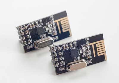
What is the NRF24L01 pinout?
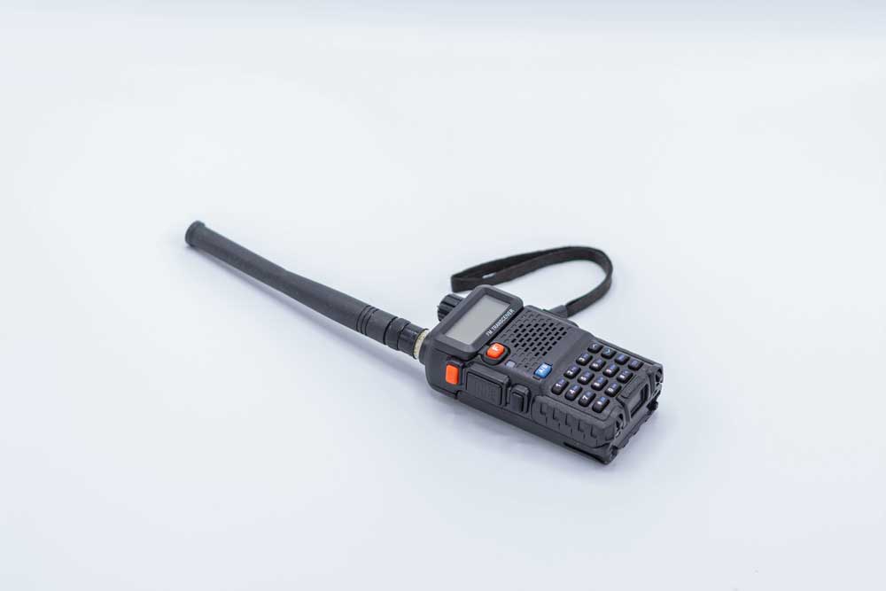
Fig 1: A Transceiver walkie-talkie
As earlier highlighted, it is a transceiver. Hence, it can operate both as a receiver and a transmitter. Also, it has a relatively low power consumption, given that it requires only 9.0mA at -6dBm output power. While in RX mode, the module involves 12.3mA, which is lesser than what an LED needs to function.
Also, the module has an extensive maximum range of up to 100m when operating in an open space with an external antenna.
NRF24L01 Pin Configuration
The table below explores the module pinout of the RF transceiver.
| Pin Number | Pin Name | Pin Use |
| 1 | VCC | It’s the module’s power supply pin via which you supply an input voltage of 1.9 – 3.9V. |
| 2 | Chip Select Not (CSN) | You should always keep an active-LOW pin at high to facilitate SPI communication. |
| 3 | Master Out Slave In (MOSI) | The terminal acts as the nRF24L01’s SPI input pin responsible for data reception from the microcontroller. |
| 4 | IRQ | It communicates with the master whenever there’s new data for processing. |
| 5 | Master In Slave Out (MISO) | The nRF24L01 SPI output terminal sends data to the microcontroller. |
| 6 | Serial Clock (SCK) | The pin receives clock pulses from the SPI bus master. |
| 7 | Chip Enable (CE) | It operates as the module enables pin. Also, it is handy in selecting whether to receive or transmit data. |
| 8 | GND | Often marked with a square enclosure for easy identification, the ground pin is handy in grounding the circuit. |
Features of NRF24L01
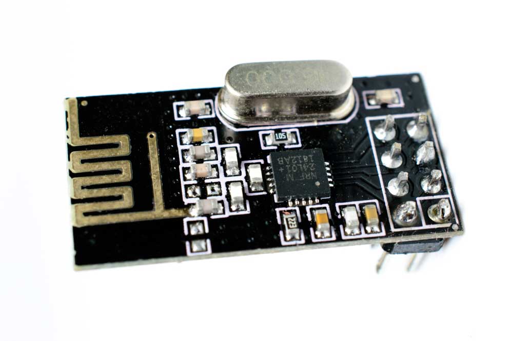
Fig 2: A transceiver chip
- It works at a power supply range of 1.9 to 3.6 V and requires 2-layer PCB and cheap chip inductors.
- Also, the NRF24L01 transceiver module comes in a 20-pin package and requires an inexpensive +/- 60 ppm crystal.
- Thirdly, the module has tolerant signal input pads of 5V and is RF-compatible with other nRF24XX modules.
- The transceiver module is also capable of frequency hopping thanks to its relatively short switching time.
- In addition, the module has an RF channel operation of 125 and a Digital interface SPI speed of between zero to 8 Mbps.
- Further, it allows Cyclic Redundancy Check and Address computation.
- Lastly, it features an Enhanced ShockBurst™ communication protocol and Auto acknowledgment & retransmits capability.
Specifications
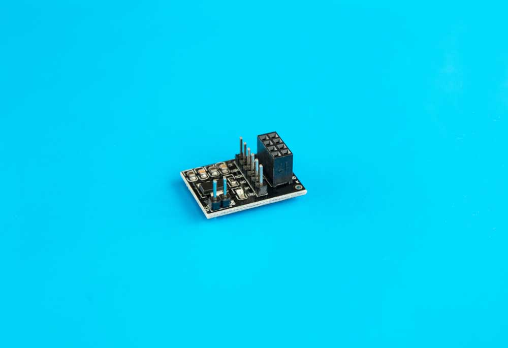
Fig 3: A NRF24L01 wireless transceiver module
- The module’s frequency range is in the 2.4 GHz band and features a 2 Mb per second maximum air data rate.
- Secondly, it operates on the GFSK modulation format and a 0 dBm maximum output power.
- Its power operation specifications include a 13.5mA maximum operating current, and while in standby mode, it requires a minimum current of 26µA.
- Lastly, It has an 800+ m full-size line of sight communication range.
How to use the NRF24L01 Communication Module
You can interface the module with all the intelligent boards and microcontrollers.
Interfacing with Arduino
The circuit diagram below represents how to connect the module to Arduino UNO.
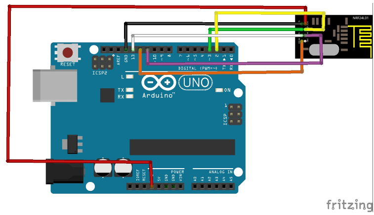
Remember that the module can work either as a receiver or transmitter.
Bi-directional Wireless Communication with two NRF24L01 and Arduino
You must run the receiver and transmitter codes on the Arduino Uno in this mode.
Also, for bidirectional communication, creating two channels/pipes is imperative. Besides, it is also necessary to define each of the lines. Note that the writing address of the primary Arduino is the secondary Arduino’s reading address and vice versa.
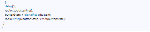
Now, use the radio. Stop listening() function, set the primary Arduino as a transmitter by running the code below.
Next, use the radio. Start listening() function set the secondary Arduino as a receiver via the code below.

Sending multiple variables in a single package
For this example, the transmitter and receiver codes are as follows:
Transmitter code
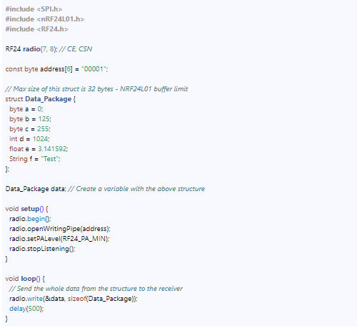
Notably, this data struct can have a maximum of 32 bytes.
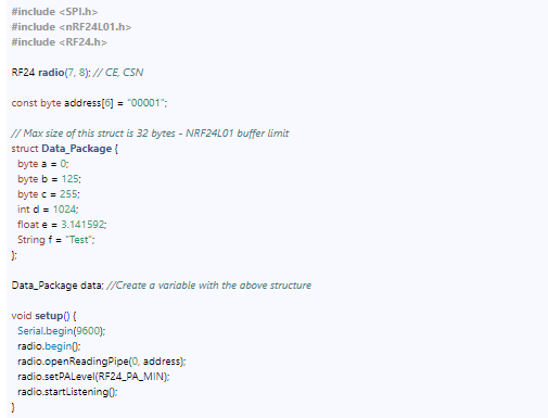
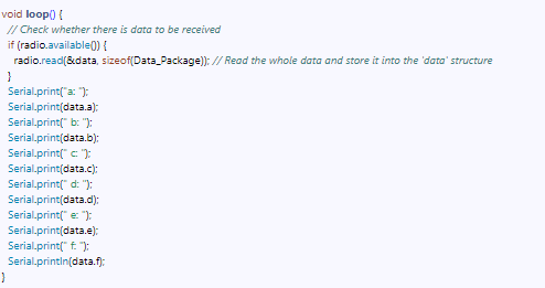
Receiver Code
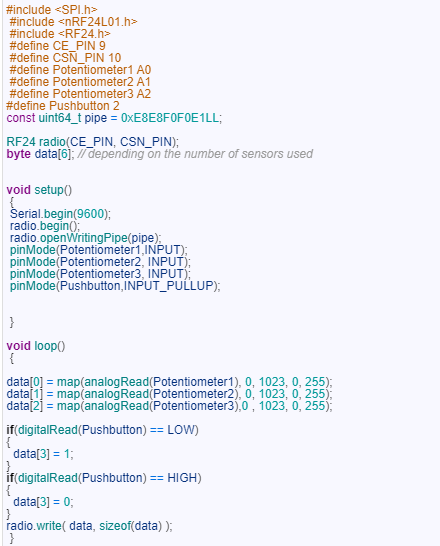
NRF24L01 and Arduino-based Sensor Monitoring
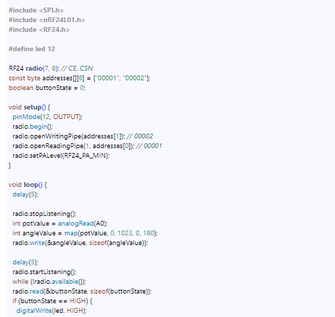
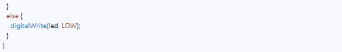
This circuit is handy in instances where monitoring and control are necessary. Thus, using the codes below, you can control the function of LEDs connected to two Arduino Uno boards.
Transmitter Code
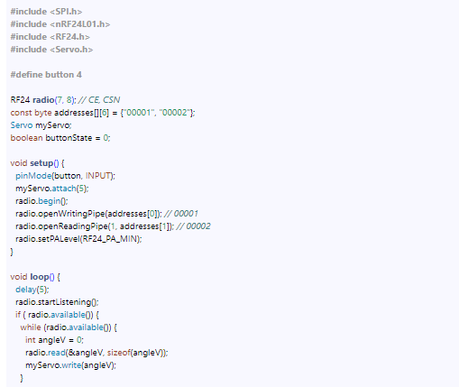
Receiver Code
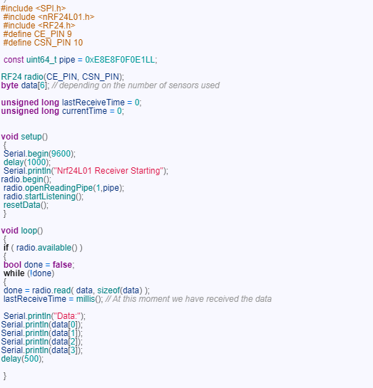
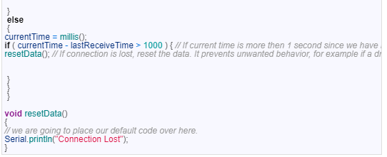
Note that the program below can control both the receiver and transmitter functions.
As a Transmitter Example
The module transmits data from one frequency channel/ transmitter address to another when operating as a transmitter. Hence, to use it as a transmitter, upload the code below.
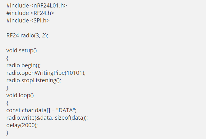
Transmitter code details
The following libraries are responsible for Arduino communication with the module as a transmitter.
As a Receiver Example
Using the module as a receiver follows a similar process to its use as a transmitter. But, three main modifications are as follows:
- The receiver requires an address channel/ address range. It was unnecessary in the former transmitter example.
- Also, the module needs an initialization as a receiver to operate in this mode.
- Thirdly, it also requires a data receipt and checking technique.
Next, you need to upload the receiver code to the Arduino IDE, which is as follows.

Application
- Useful in RF Remote Controllers and mesh networks.
- Also, it’s essential in wireless transceiver module applications and advanced communications applications.
- Thirdly, it is helpful in VoIP headsets, Wireless PC Peripherals, and game controllers.
- Finally, it is handy in Asset tracing systems, Ultra low power sensor networks, and active RFIDs.
Conclusion
We’ve comprehensively covered the features, pinout, and applications of NRF24L01 by Nordic SemiconductorThThat’s all for today, but for additional queries, talk to us we’ll give you a response promptly.


