TM1637
Source: Arduino platform
Are you looking for a way to display digits on your Arduino microcontroller? Then, a TM1637 4-Digit 7-segment display is what you need.
You can use this device to design clock circuits and other applications that display numbers.
However, a regular 4-digit 7-segment display requires twelve pins and tons of wiring. Luckily, the TM1637 reduces the number of pins to four.
Two pins handle power control while the other two pins control the segments.
Thus, in this article, you’ll learn everything about the TM1637 and how to interface it with an Arduino board.
Are you ready? Let’s get to it.
Contents
What is the TM1637?
LED Display
Source: FreeSVG
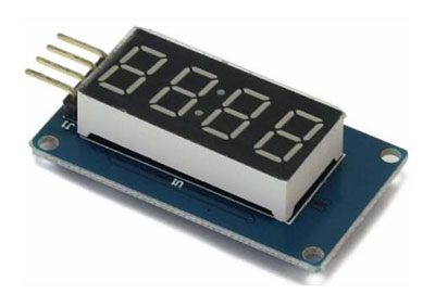
The TM1637’s design allows you to display numbers. Also, the module features four 7-segment displays that work together to create numerals. The TM1637 module works based on the TM1637 IC, hence the name TM1637 display.
TM1637 Pin Configuration
The TM1637 has four terminals, with each terminal having a different function. Check the image below to find out the functions of each pin.
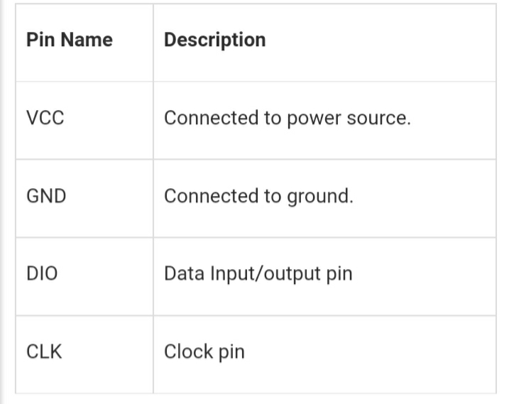
TM1637 Pin Configuration
TM1637 Features and Specifications
Here are the features and specifications of the TM1637 display:
- Has a portable size
- Features a 3.3v – 5.5v operating voltage
- It also has up to eight luminance levels you can adjust
- Plus, you get access to four alpha-numeric digits
- It has an 80mA active current consumption
- The operating temperature is between -10°c to +80°c
- It also comes with a two-wire interface

How the TM1637 Module Works
In this module, you can only establish communication with two pins, including the DIO and CLK pins. Plus, you can send or receive data on this module from these two pins.
Hence, you will send the numbers you want to display on the TM1637 interface in a serial data form. Also, you can only operate this module with a +5v regulated power supply. Anything higher than that may cause irreversible damage.
To establish communication, you need to connect the CLK and DIO pins to any available GPIO pins of your microcontroller. It will help develop serial data exchange with some programming.
Nevertheless, serial data exchange is a complex process. But you can make it easier by downloading libraries, which help with data transmission.
Also, you need to download these libraries and use them in your application programs. You can find these libraries on different websites.
Once you include the header, the controller will communicate on its own and send the characters you want to display to the module.
When the TM1637 IC receives the data from the controller, it drives the four display segments via the code. Then, the four segments will display the characters you want.
Interfacing the TM1637 4-Digit 7-Segment Display with Arduino
Before we learn how to interface the TM1637 with an Arduino, you first need to understand the basics of a 7-segment display.
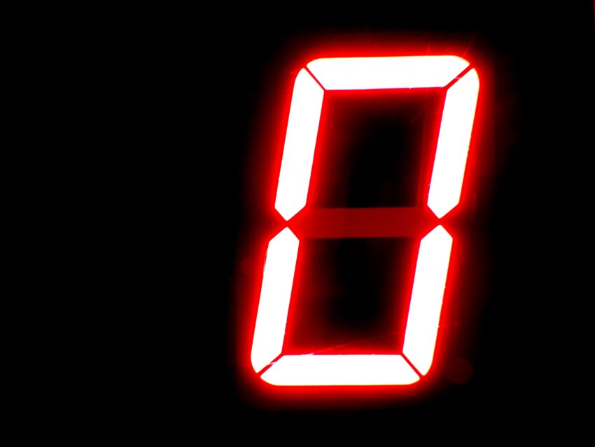
7-Segment Display
Source: Pixnio
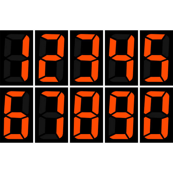
7-segment displays feature seven LEDs, which line up to form a specific pattern, usually the shape of an eight. Each LED is what we call a segment.
Lighting up a segment forms part of a numerical digit, hex, and decimal. You can label each segment from A to G. When you set a component HIGH or LOW, you can generate your desired character.
TM1673 Module Hardware Overview
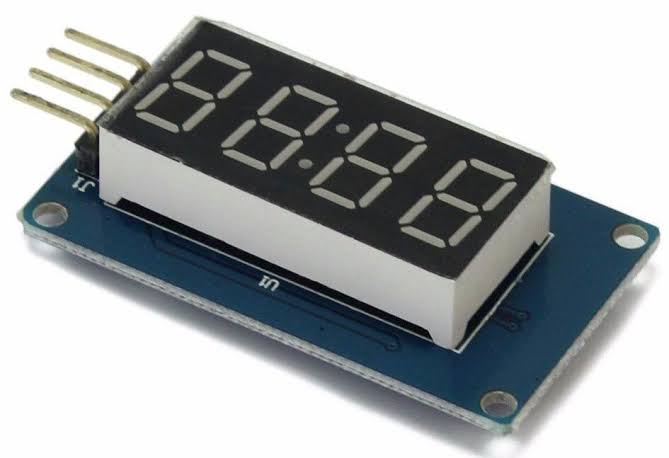
The TM1673 comes with a low-cost serial LED driver and has various functions, including LED brightness control and ON/OFF control. It can also access each of the segments.
It also features four 0.36 7-segment displays that show temperature or sensor data, with a middle colon that makes it easy to create time-based or clock projects.
Wiring the TM1637 Module with Arduino UNO
Connecting your TM1637 module with an Arduino UNO is simple. You only have to connect four wires, including two for controlling the display and two for power.
You can safely power the module with the Arduino’s 5 volts output. You’ll also connect the DIO and CLK to the Arduino’s pins 3 and 2.
Also, you don’t have to use any critical pins on the Arduino because the TM1637 does not need any specific pins to work. So, you’re free to change your pin connections but be sure to change it in your code.
Library Installation
You’ll need a library to communicate with the TM1637 chip, as we mentioned earlier. There are various libraries available, but we’ll be using one written by “Avishay Opaz.” You can get to the Library here.
The Library comes with different functions that allow you to control the TM1637 display easily. You have to input the number you want to display, and it does the work for you.
Here’s how to install your TM1637 Library:
- First, open your Arduino IDE and navigate to Sketch > Include Library> Manage libraries.
- Then, wait for the Arduino library manager to download the libraries index and update your list of installed libraries.
- Next, search for TM1637 and choose the Avishay Opaz library.
- Now you can click Install to start installing the Library.
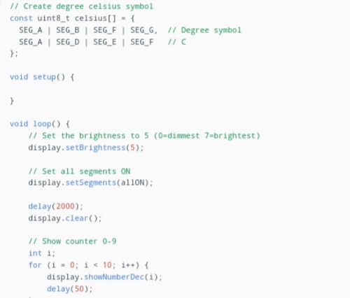
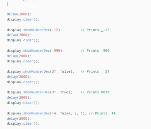
Arduino Code
Here is a basic code for a test program that goes through various routines. You can upload this code to your Arduino:
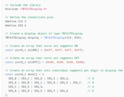
The Arduino Code
Arduino Code
Arduino Code
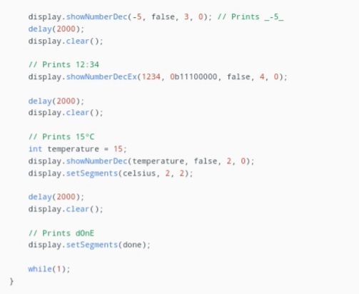
The Arduino Code
Arduino Project – Building a Clock with TM1637 and DS3231
You can pair the TM167 module with a DS3231 RTC module to make a working twenty-four-hour digital clock.
First, connect your TM1637 display and DS3231 RTC module and upload the following code.
The code uses the Adafruit RTC library and displays time in a 24-hour format.
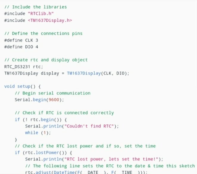
Arduino Project Code
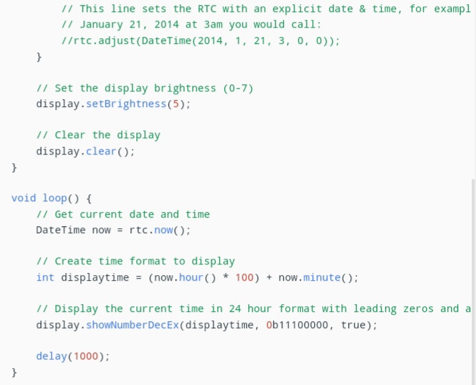
Arduino Project Code
Final Words
The TM1637 display module is one of the best modules you can use for your LED display applications.
It’s durable, versatile, and can withstand high operating temperatures while giving out optimal performance.
Plus, it takes away the complexity of wiring a 12-pin display module by featuring only four pins. And it has different libraries that make communicating with the TM1673 chip easier than other modules.
It also works for several applications, including time-based and temperature projects.
If you have any questions, feel free to reach us, and we’ll be happy to help.


