Generally, an Xbee radio frequency/ RF module is a cost-effective and easy-to-use module in wireless technology. Often, you’ll find them device network applications like asset tracking, medical devices, industrial automation, and smart cities. In today’s XBee tutorial, we’ll use an Arduino UNO board and two XBee modules (transmitter and receiver) to demonstrate wireless communication.
Contents
Pre-requirements
Some of the main components you will need for the Digi XBee and Arduino project are as follows;
Hardware
- One 9V battery (optional)
- One 9V Barrel Jack Adapter (also optional)
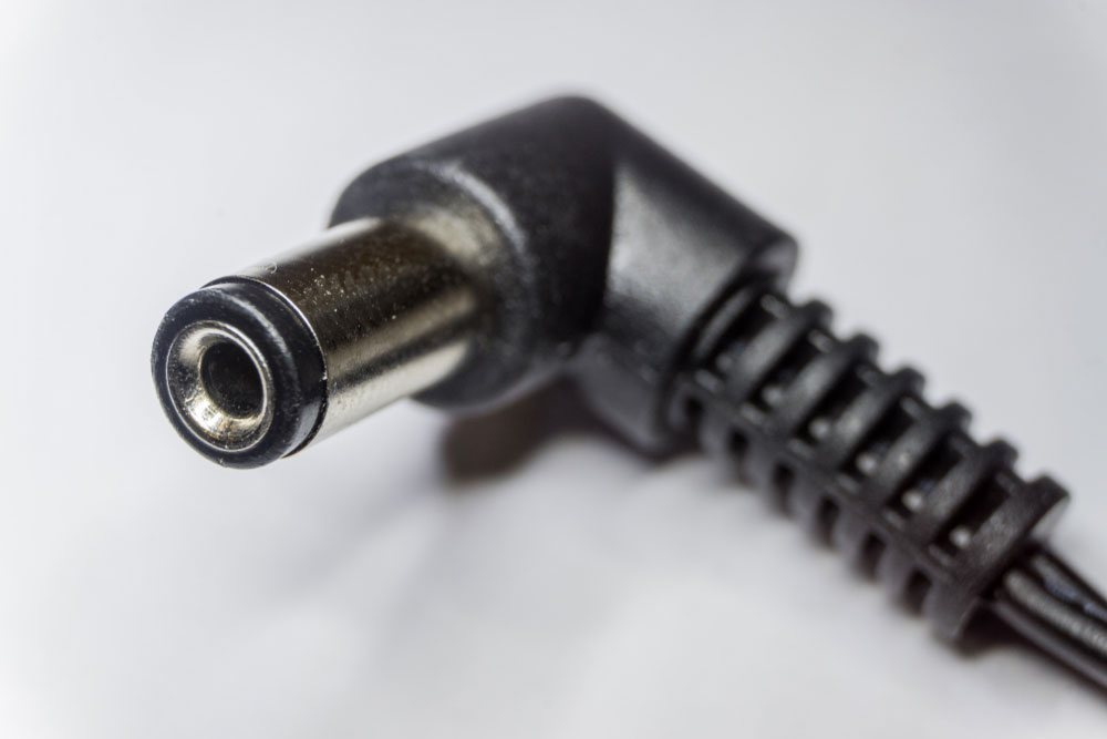
(Barrel jack adapter)
- One XBee shield
- One XBee explorer (can be Explorer Serial, Explorer USB Dongle, or Explorer USB)
- Two XBee Series-1 or Series-3 (with an 802.15.4 protocol configuration)
- One Arduino UNO board or Leonardo
- A PC with an installed X-CTU software
- Potentiometer
- LED, button, 5.1k ohm resistor, 100ohm resistor (one of each)
- 0.1’ male headers
- Jumper wires
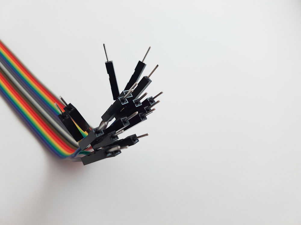
(jumper wires)
- A large breadboard (or two small ones)
Software
- CoolTerm
- FTDI Drivers that communicate with your XBee explorer board
- Arduino IDE software
Step 1: Program the XBee’s
Our first process involves using CoolTerm to initiate a connection between the two XBee.
- Insert one Xbee module into the Explorer board, then use a USB cable to connect it to your PC.
- Tap the “Option” button when CoolTerm is open. Next, below the “Serial Port Option,” click the “Port” drop-down menu, then pick an Explorer (i.e., USB serial-AD025ES5). However, if you don’t see the name, push the button that says “Re-Scan Serial Ports.”
- Press the “Ok” button to start working on the XBee.
- To set up your XBee’s, you need to send the following four commands
ATMY: It’s the address for the XBee and must be dissimilar for the two XBees.
ATDL: It shows the address of the place to go (the ATMY address of the other XBee).
ATID: The PAN ID is a network that the XBee’s will use to talk to each other. Both XBees should have the same setting for this.
ATWR: It saves the XBee’s changes.
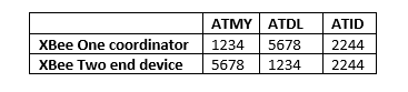
Your final setup should appear like the table below;
Click on “Connect” and begin writing +++ but don’t hit enter. You’ll see an “OK” if you stay for a second (the “OK” implies that your XBee can now get commands. Failure to write a command within the first 10 secs changes the XBee’s state, and you’ll need to rewrite +++.)
Then, systemically write the following addresses and press enter after each of them.
- ATMY1234
- ATDL5678
- ATID2244
- ATWR
Afterward, click on “Disconnect.”
Follow steps five through ten for your second XBee. However, note that you’ll type ATMY5678 and ATDL1234, which is contrary to what you did for the first XBee.
Now, shut down CoolTerm and unplug the XBee Explorer from the computer’s USB port.
Finally, your XBee is now all set with the configuration below:
For XBee receiver;
- Baud rate at 9600bps
- CE – Endpoint
- ID – 1001
- CH – C
For XBee transmitter;
- Baud rate at 9600 bps
- CE – Coordinator
- ID – 1001
- CH – C

Step 2: Program the Arduino
Your pin configuration options should be as follows;
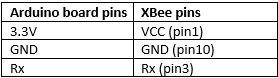
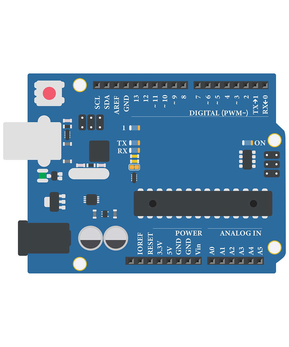
(Pinout in Arduino board)
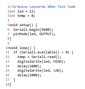
Generally, there’s an inbuilt LED (digital pin13) on the Arduino. Here, we’ll show you how to cause the LED to light up after the Arduino gets a wireless signal.
- First, put an XBee on a shield, and then transfer the shield to your Arduino. You can select between UART and DLINE using a switch on the shield. Next, put the switch in UART mode.
- Connect the Arduino to your PC and proceed to the Arduino board software.
- Select your serial port by pressing “Tools” and “Serial Port.” It’s tty.usbmodem1411 for me (yours may have a similar outlook but with a slight difference in digits).
- Afterward, select your board by going to “Tools” and then “Boards” (UNO, Leonardo, etc.
- Lastly, please copy then paste the code below. The former is for Arduino UNO, whereas the latter is for Arduino Leonardo). Finally, click the upload button.

Note; Ensure you keep the Arduino continuously connected to the PC.
Step 3: Programming and Testing XBee communication using Arduino
- Plug the second XBee into an Explorer before placing it on your PC.
- Secondly, open CoolTerm, go to the Options menu, pick the Explorer board, then press “OK” (similar to steps two and three in step one).
- Hit the button that says “Connect.”
- Note something down even though you won’t view whatever you write anything in the serial monitor screen. However, the Arduino’s pin13 LED should flash for a sec.
- All done! Now, your two XBees can have simple communication with one another.
Conclusion
Kindly contact us if you have suggestions for other solutions, questions, or trouble setting up your wireless module.


