A capacitor on the circuit board is pretty essential. In truth, the component handles electrical energy storage, which every device needs to work.
However, capacitors may develop issues over time. For example, these devices may blow up or get damaged by excessive electricity or heat.
In such situations, you must make replacements to ensure your board runs smoothly. But how do you replace a capacitor on a PCB?
Although the process is tricky, we’re here to run you through the process.
Also, this article will discuss how to detect a damaged capacitor.
Contents
How do You Test a Capacitor on a Circuit Board?
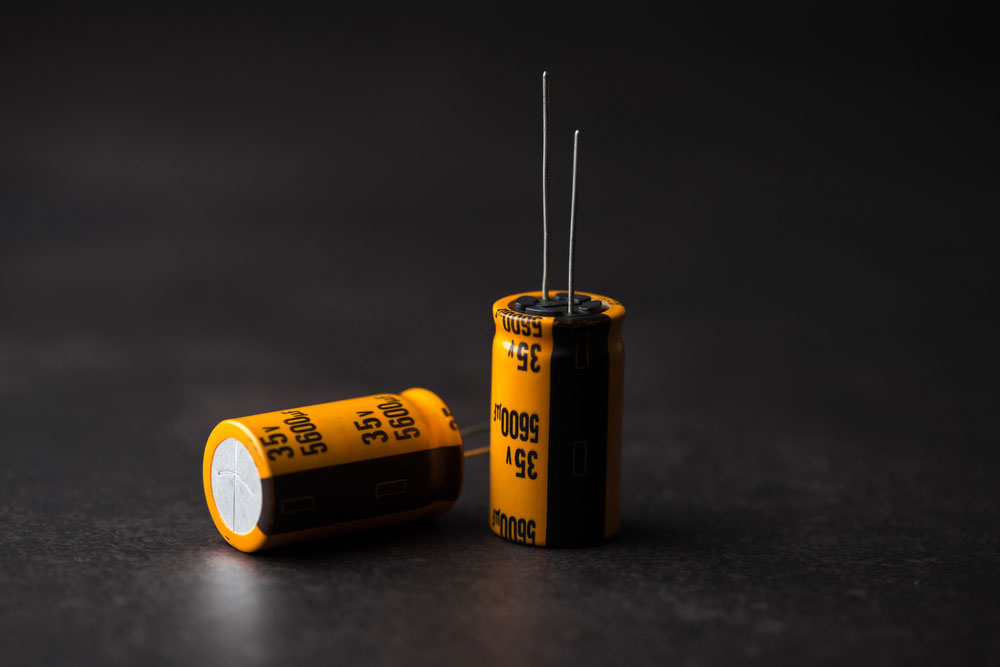
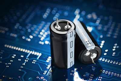
Capacitors
There are many reasons why you need to test your capacitor. For instance, you may want to know if it’s dead, good, open, or short.
But you can’t achieve this if you don’t know any testing methods.
So, here are three ways to test your capacitor with multimeters and voltmeters.
Methods for Testing and Checking a Capacitor
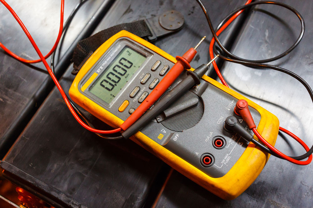
Method 1: Capacitor Test using A Digital Multimeter

Digital Multimeter
Before you start, ensure your digital multimeter is in resistance or Ohm mode.
Here’s how to do this project:
- First, discharge the capacitor before connecting your multimeter.
- Then, change your meter’s settings on the Ohmic range to at least 1000 Ohm/ 1kΩ.
- Next, take your multimeter’s probes, and connect them to the capacitor’s terminals. Link negative to negative and positive to positive.
- Check your multimeter’s screen. It should show some numbers before switching to the next step. Ensure you note or memorize the values.
- After a few seconds, the multimeter will switch back to OL (Open Line) or Infinity.
- Lastly, your capacitor is in good condition if it shows the same result for every test. If it doesn’t, the component is faulty.
Method 2: Capacitor Test using an Analog Multimeter
AVO multimeter
Similar to method 1, ensure your AVO is in resistance or Ohm mode before following the next steps.
- Start this method by discharging the capacitor.
- Next, grab your AVO meter and rotate the knob to choose OHM mode. Remember always to select higher ranges.
- Then, connect the meter’s probes to the capacitor’s terminals. Plug -ve to COM and +ve to positive.
- Ensure you note or memorize the readings for the next step.
- The AVO will show low resistance if you have a short capacitor.
- Additionally, no movement will occur on the Ohm scale if the component is an open capacitor.
- Lastly, good capacitors will start with low resistance values but climb slowly towards infinite.
Method 3: Capacitor Test using a Multimeter in Capacitance Mode
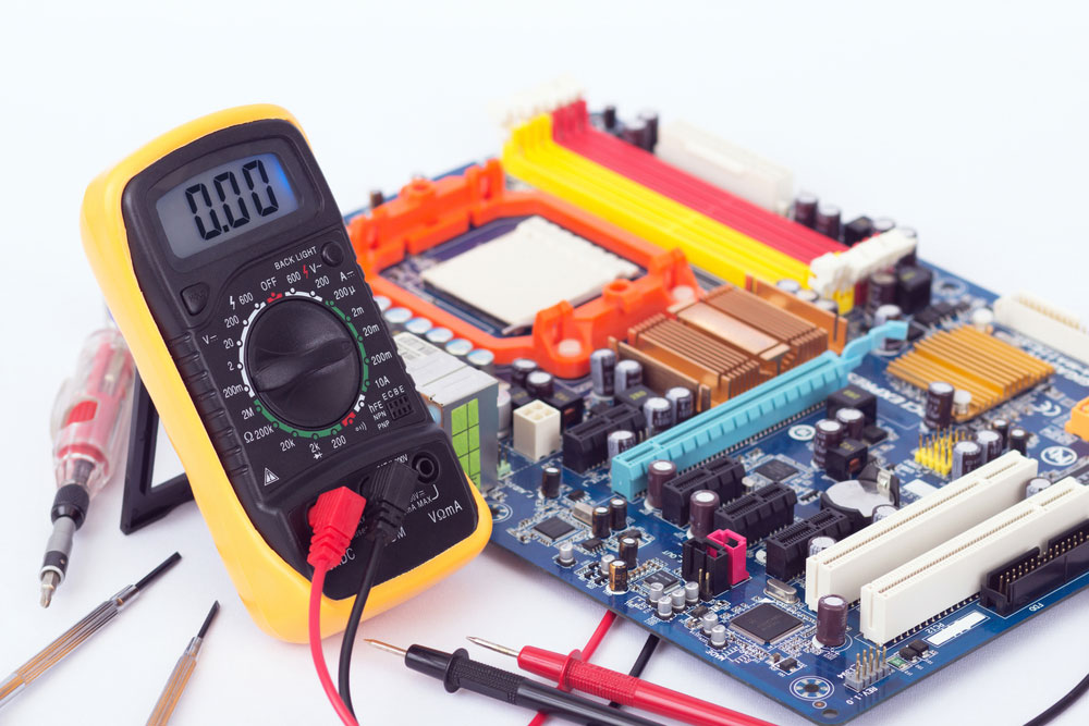
Multimeter testing circuit
You can only use this method if your multimeter has Farad features.
Also, you can use this mode to test smaller capacitors.
And you can rotate your device’s knob to select Capacitance mode.
- First, discharge your capacitor and remove it from the circuit board.
- Grab your multimeter and set it to Capacitance “C” mode.
- Next, take your probes and connect them to your capacitor’s terminal. Again, red matches with positive, while black goes to Negative.
- Check your multimeter’s readings. The component is in good condition if close to the value printed on the capacitor’s body.
- If the readings go below or show no values, you have a dead capacitor.

How to Replace a Capacitor on a Circuit Board

Woman working on a PCB
Step 1: Know when to Make Replacements
Damaged capacitors are notorious for causing many issues.
So, you can use these signs as an early warning and plan for a capacitor change.
- The device is not turning on.
- Periodic switching on and off
- Screen flickering–if your device has a display.
These are a few problems, but you can suspect the capacitor if your board starts acting up.
Step 2: Gather your Tools for the Process
You’ll need the following equipment to change your board’s capacitor.
- Soldering mask and iron
- A new capacitor with matching values
- A tool to pry your device’s casing open.
Step 3: Find the Damaged Capacitor
Start by switching off your device and unplugging it from the power supply.
Then, access the PCB by opening the casing with your tool (screwdriver or hex wrench).
Note: Ensure you keep the screws safe so they don’t get lost.
We recommend accessing your device’s user manual if opening the casing is tricky. After locating the circuit board, place it under proper illumination. At this point, it’s easy to identify the damaged capacitor. Three things to watch out for include:
- Corroded body or sipping fluid
- The damaged capacitor leaked out brownish fluid
- Leads popping out of the capacitor
Move to the next step if your capacitor has any of the above signs.
Step 4: Disconnect the Damaged Capacitor
It’s crucial to check your capacitor’s temperature rating, voltage, and capacitance before removing and replacing the device.
Then, find the soldering point behind the capacitor and press it with a heated soldering iron.
Further, hold down the heated iron until the capacitor loosens from the circuit board.
Next, do the same on the other side to free the wiring and detach the capacitor.
What happens when the solder joint is too thick?
You can use a soldering wick to clean any extra solder at the back of the board.
Then, use the soldering iron again to disconnect the component.
Note: Don’t rush. This step requires patience to ensure maximum efficiency.
Step 5: Install a Fresh Capacitor
First, mount the capacitor to your PCB. While at it, ensure the capacitor has a similar height to the previous one.
Hence, it would be best if you trimmed the leads of your new capacitor.
Then, position it carefully on the solder holes.
In addition, ensure your capacitor stays in a position that achieves the correct polarity.
Then, grab your soldering iron and use it to secure the capacitor to the joint.
The old soldering joint will suffice for the new one. Lastly, repeat the soldering process on the other side before placing the PCB back in its casing.
Rounding Up
Capacitors are must-have components that every engineer needs to build a functioning PCB.
In addition, they can store electricity and even charge for the benefit of the board.
However, capacitors start to act up when they get damaged.
Plus, it’s easy to detect and replace a damaged capacitor with the above steps.
Do you have more questions? Feel free to reach us, and we’ll be happy to help


