Contents
Introduction to the Arduino Nano
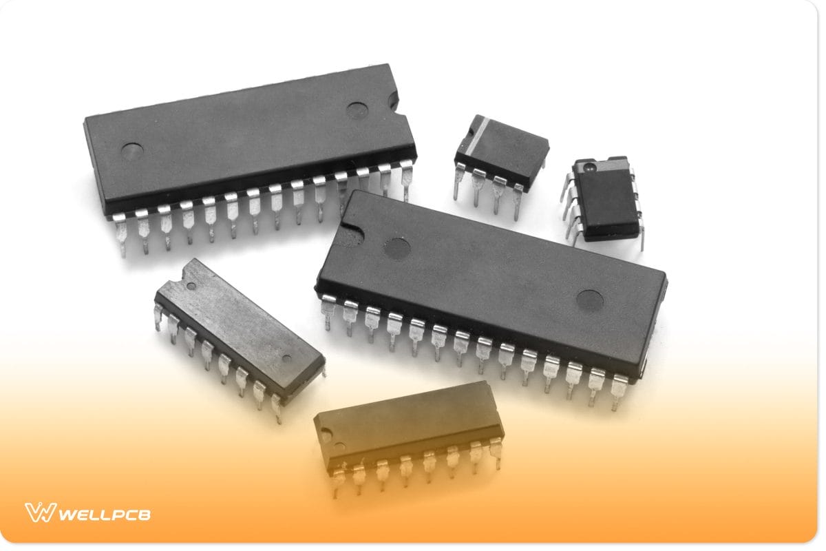
(Also known as PDIP (plastic DIP))
The Nano is one of Arduino’s smallest microcontrollers. With dimensions of 45mm (L) X 18mm (W) and a weight of seven grams, it’s a more compact version of the Arduino UNO.
Both boards are built with the ATmega328P microcontroller unit (MCU).
However, where the Arduino Nano uses a Type-B Micro USB for its power source, the Arduino Nano has a DC power jack (in addition to a standard USB port).
There are two versions of the Arduino UNO R3. One uses a Dual-inline Package (DIP) and has 28 pins; the other uses Surface Mount Technology (SMD/SMT) and has 32 pins.
The original Arduino Nano is only available with 32 pins.
Ultimately, the Arduino Nano is a more portable version of the Arduino Uno (R1-R3) and shares many of the same specs, including its breadboard friendliness.
In some instances, you should be able to use both boards interchangeably. However, the Nano should work better for more compact, lightweight projects. Let’s look at the key features of the Nano.
Key Features of the Arduino Nano
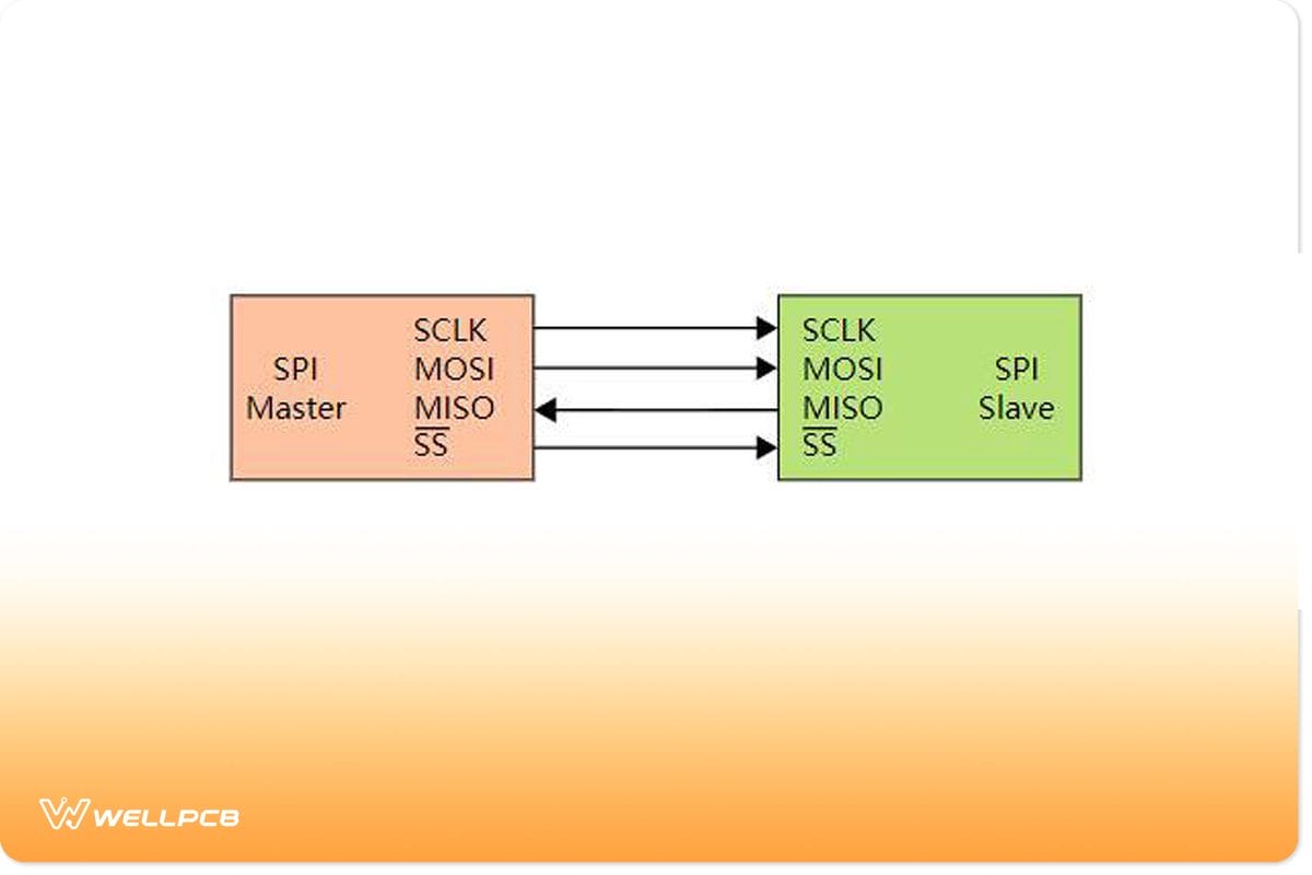
(Basic SPI bus example)
| ARDUINO NANO | SPECIFICATION |
| Microcontroller | ATmega328P |
| CPU Flash Memory | 32 KB (2 KB used by Bootloader) flash memory |
| Architecture / Processor | AVR 8-bit |
| SRAM | 2 KB |
| EEPROM | 1 KB |
| Clock Speed | 16 MHz clock speed |
| Operating Voltage Source | 5V |
| Analog I/O Pins | 8 |
| Input Voltage | 7V-12V |
| DC Current per I/O Pins | 40 mA |
| Digital I/O Pins | 22 |
| Pulse-width modulation (PWM) output | 6 |
| Power Consumption | 19 mA |
| PCB Size | 1.8 cm X 4.5 cm |
| USB | Type-B Micro USB |
| ICSP Header | YES |
| Communication | IIC, SPI communication, USART |
| Weight | 7 grams |
| Programmable | Arduino IDE |
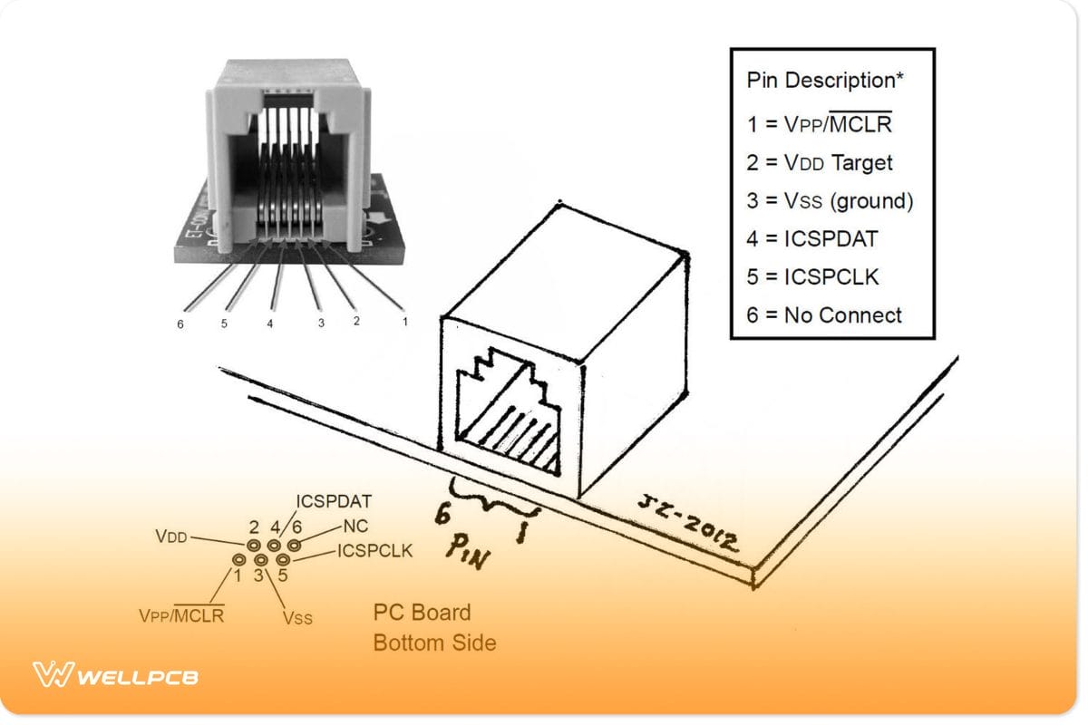
(RJ11 turn ICSP PIC programmer)
Unveiling The Arduino Nano Pinout
Whether it’s a soil moisture sensor or a smart door alarm, you’ll need to understand the Arduino Nano’s pinout to successfully execute these projects. The pinout is what allows the Arduino Nano to be breadboard-friendly.
As with most (if not all) ATmega328P microcontrollers, the Arduino Nano has a total of 32 pins.
Thirty of these pins are male headers (physical pins) that run along the lengths of the circuit board. These pins fall under three main categories: power, analog, and digital.
The power pins (VIN, 5V,3V3, GND) provide the microcontroller with electric energy, while the others enable communication between the Nano and external components.
Arduino Nano Pins
(Arduino Nano function pins arrangements)
| Pin Number | Pin Name | Pin Type |
| Digital | ||
| 1 | D1 (TX1) | Digital I/O Pin 1 |
| 2 | D0 (RX0) | Digital I/O Pin 0 |
| 3-14 | D2-D13 | Digital I/O Pin 2-Digital I/O Pin 13 |
| 15 | Reset | Reset |
| 16 | GND | Power (Ground) |
| Analog | ||
| 1 | +3V3 | 5V USB Power |
| 2-9 | A0-A7 | Analog Input 0-Analog Input 7 |
| 10 | +5V | +5V Power Rail |
| 11 | Reset | Reset |
| 12 | GND | Power (Ground) |
| 12 | VIN | Power (Voltage Input) |
| ATmega328 Debug Pins | ||
| 1 | PB0 | Serial Wire Debug |
| 2 | PB1 | Serial Wire Debug |
| 3 | PB2 | Serial Wire Debug |
| 4 | PB3 | Serial Wire Debug |
| 5 | PB4 | Serial Wire Debug |
| 6 | PB5 | Serial Wire Debug |
Powering Up Your Arduino Nano
(Arduino Nano powered using mini USB)
You will need to power Arduino Nano up to run your first application which will require you to understand the Arduino Nano’s power modes. These power modes can keep your Arduino circuit board safe, specifically from power damage.
- Mini-B USB cable Connector – Connect the mini USB cable power jack to the pin and let it draw power from any source from which a connection occurs. On the one hand, this option also allows you to draw power from any device that specifically supports USB connector micro USB.
- VIN pin – 6-20V unregulated external power supply specifically passes through the pin to the board to power it. Afterwards, the power goes through regulation by the Nano board to 5V voltage suitable for the power circuit board’s operation by a board voltage regulator.
- 5V pin– equally important. If you have a regulated power supply source of 5V, here is where the power connection occurs. Hence, this source also supplies the power to the circuit board directly; hence, any external power source overload or external interrupts can specifically damage the Arduino microcontroller board.
- 3V3 – The minimum voltage generated by the inbuilt Nano board voltage regulator.
- GND – The ground pin on the nano board.
Communication Protocols
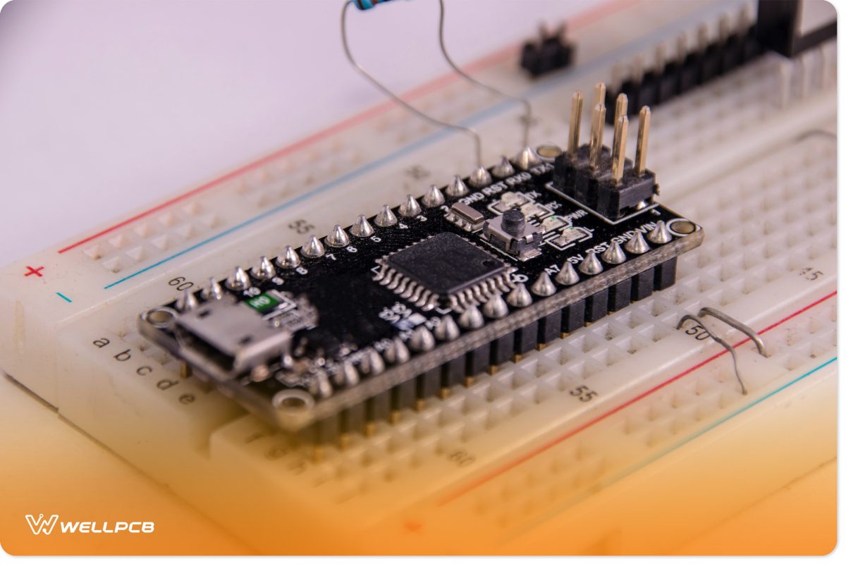
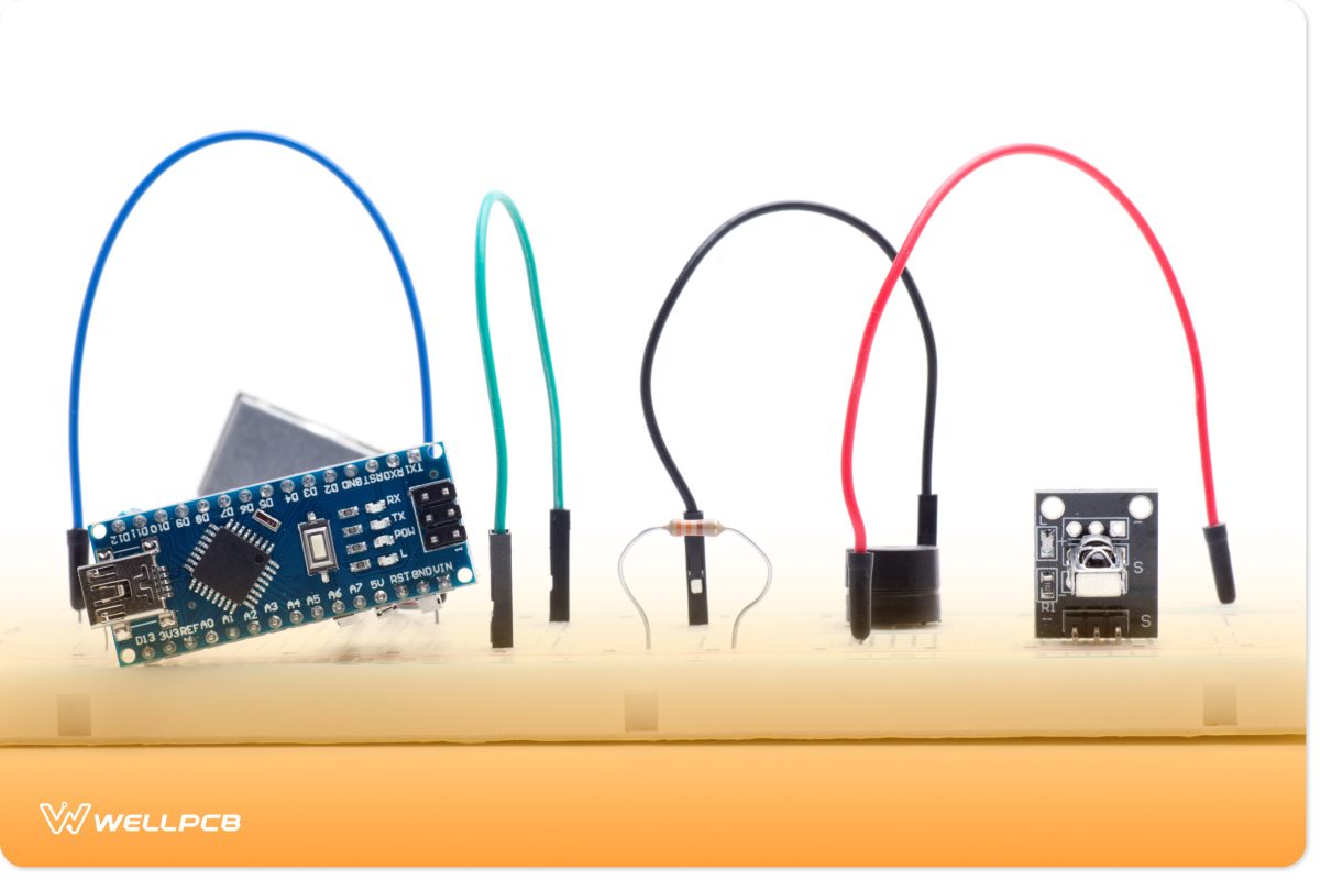
(Arduino Nano set-up on a breadboard)
The TX / D1 and RX/D1 are both digital I/O pins responsible for transmitting and receiving serial data, respectively.
In addition to these pins, the Arduino Nano features two reset pins and a single reset button.
D0 to D13 are all 14 of the Arduino Nano’s General-Purpose Digital Input-Output (GPIO) pins.
The pinMode(), digitalRead(), and digitalWrite() functions allow you to configure the pins as per your project requirements.
The Arduino Nano’s GPIO pins feature an internal pull-up resistor that ranges from 20Ω to 40Ω.
However, these are not connected by default. The GPIO pins can source 40 mA to power the microcontroller.
Pin D2 and D3 are digital I/O pins used to interrupt the microcontroller program in case of an emergency or when a more important function needs execution.
D3, D5, D6, D9, and D11 pins support Pulse width Modulation. This allows them to control and adjust the speed of fans, alter the brightness of LEDs, etc.
A0 to A7 are the Nano’s eight Analog input pins. They feature an 8-bit analog-to-digital converter (ADC) feature. The analogRead() function allows you to read data from these pins,
ICSP and SPI
The Nano also features a six-pin header situated on a single side of its width (opposite the USB jack).
These pins are used for In-Circuit Series Programming (ICSP) through Serial Peripheral Interface (SPI) communication.
You won’t be able to upload a bootloader to your Nano without them. Three of these header pins allow you to transfer data (MISO, MOSI, and SCK), while the others are power pins (5V, GND, and Reset).
If you look closely, you’ll notice that these pins correspond and share a connection with the main headers of the board.
Mainly the D11 Master Out Slave In (MOSI), D12 Master In Slave Out (MISO), and D13 Serial Clock (SCK) pins.
The only SPI-related pin that’s missing from the header is the D10 Signal and Systems (SS) pin.
I2C and Everything In-Between
The built-in LED (13) pin controls the internal LED embedded in the Nano’s circuit board, allowing you to turn it on or off.
The analog A4 (SDA) and A5 (SCA) pins enable Two-Wire Interface (TWI) and Inter-Integrated Circuit (I2C) communication. AREF is an Analog voltage-to-digital Conversion (ADC) reference.
Conquering Arduino Nano Pinout Challenges
Robotics is a complex marriage between software development and electronics engineering. Hence, troubleshooting the Arduino Nano can be complex. Your projects could fail because of a software or hardware issue (or a combination of the two).
For instance, what you might think is a pinout issue could be a computer or IDE issue (and vice versa). It’s important to work through all the endpoints to find the issue. Some common IDE to Arduino Pinout Nano connection issues are as follows:
- Absent Serial Communication Drivers
- Incorrect Port Selection
- Absent Bootloader
- Incorrect Board Configurations
While you can correct the above issues from your computer, they aren’t the only ones you’re likely to encounter.
You should consider building your own personal Arduino troubleshooting kit. This will allow you to inspect and troubleshoot hardware issues.
The kit should (at the least) feature a magnifying glass, a multimeter, and a soldering iron.
Before you pursue any projects, make sure you’ve read Arduiono’s official documentation.
It contains important information that can make it easier to work with and troubleshoot the Arduino Nano. Here are a few additional tips you might find helpful:
Best Practices for Maintaining Peak Performance
Ensure that your Arduino Nano and its pins are free from dust, dirt and any other debris. These can cause connectivity issues.
Inspect the headers and connectors for any damage before you attempt to connect them. Be wary of any loose fitting or damaged wires.
These can result in not just malfunctioning projects, but damage to your Arduino Nano and the equipment it’s connected to.
Thus, replace them as soon as you find them. Avoid using excessive force when connecting your Nano to its external components.
Exercise proper soldering technique when using a blank PCB board (bare board). Keep your work area clean, and be weary of static discharges. Static can completely damage your microcontroller unit, leaving it non-functional.
Conclusion
Despite it being over a decade old, the Arduino Nano is still a useful tool for IoT, smart home and robotics projects.
However, executing these projects successfully will require you to have an intimate understanding of the Arduino Nano’s pinout.
This means understanding the type of protocols and interfaces it can communicate through. Are the number of GPIO pins the Arduino Nano offers enough?
Does it meet your project’s SPI and analog pin requirements? These are all questions that can be answered with the aid of the above guide.
Why not take things further and design your own testing board? Contact one of our experts today and learn how we can help you get started on this journey.