Most modern electronics require manipulated current and voltage to function correctly. One could argue that Most modern electronics need manipulated current and voltage to function correctly. One could say that continuous output current manipulation is the primary purpose of all circuitry. Nevertheless, there are a variety of devices and components that help achieve the goal of voltage stabilization. One of these devices is the voltage regulator. This guide will explore the automatic voltage regulator project and how you can build an automatic voltage circuit of your own.
Contents
How Do Automatic Voltage Regulators Work?
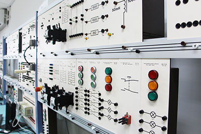
Circuit Voltage regulator
Voltage regulators are electrical devices that facilitate a constant voltage. There are three main types of voltage regulators:
- Electronic voltage regulators
- Mechanical voltage regulators
- Electromechanical voltage regulators
Most modern voltage regulators are either electronic or electromechanical. Until creating automatic voltage regulators, people had to operate voltage regulators manually through switches and physical cut-offs.
Thus, we integrated automatic voltage regulators to ensure a stable output voltage with as little human intervention as possible. This is why we use them primarily for electric generators in power stations.
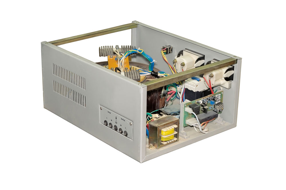
Automatic voltage regulator adjustment
Applications of Automatic Voltage Regulators
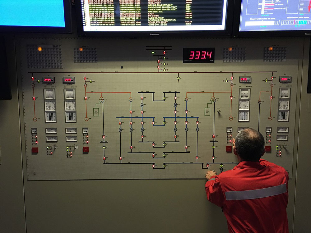
Power station generators tend to deal out massive amounts of power. As such, we need to stabilize the voltage of this power to prevent failure or damage to equipment. This is where automatic voltage generators come in.
The AVR will ensure that the generator is dispersing power at a specific voltage. If it dips or goes beyond a certain set point, the AVR will send an error signal and adjust the actual output voltage.
Of course, it will depend on the average input voltage. However, in cases where multiple generators are running in parallel, a set of AVRs will be there to ascertain that all generators produce a stable and constant power output.
Nevertheless, central power station generators aren’t the only systems that require voltage stabilization through an AVR. We can also use voltage generators to protect against any voltage fluctuation in everyday electronic devices too. For instance, we can use them in laptops, medical devices, automobile alternators, automobile power systems, data centers, and other commercial applications.
Most voltage operators allow a capacity of up to a kilowatt of AC operating power. Additionally, they will enable you to alter the control of output voltage depending on device requirements. As such, an AVR will have different steps to accommodate for variable voltage. Thus, the purpose of the voltage regulator is to ensure steady voltage. The voltage regulator can also regulate alternating current to direct current.
Automatic Voltage Regulator Circuit
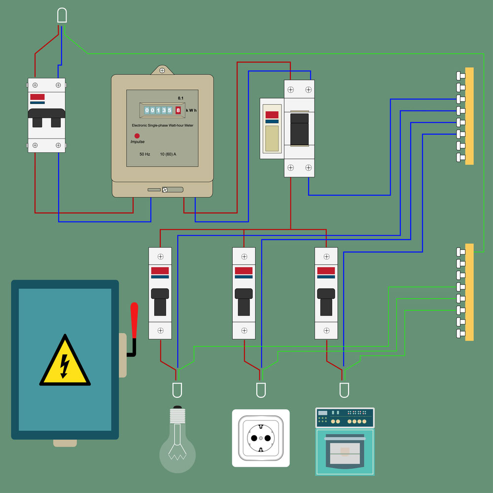
Electric circuit with feedback voltage regulator
In this section, we’ll cover a simple automatic voltage regulator circuit design.
The electronic components are as follows:
Parts List
- 120V AC Input power
- Bi-directional switch
- 10A Fuse
- Double Pole Double Throw (DPDT) Switch with four ends
- Transformer with 220 turns (6 layers) with eight secondary windings (7x 55 turns and 1x 60 turns)
- 500mA Transformer
- Relay
- 8-step rotary switch
- Red Neon lamp/diode
- Green Neon Lamp
- 100μ 25V Capacitors x 2
- IN4007 diodes x 2
- 5KΩ resistor
- 5K preset resistor
- 5K preset variable resistor
- 2V Zener diode
- BC547 transistor
- Voltmeter

Construction of Automatic Voltage Regulator Instructions
The circuit will require a 120V power source with a live and neutral input. The neutral line will connect to a standard switch and then run through to the first end of the DPDT switch. Next, the 120V line will connect to the fuse and run through to the 220 turn transformer.
The live line from the mains will then connect to the primary winding of the 220 turns transformer. The first secondary winding (with 60 turns) must connect to the first step of the rotary switch and the third ending of the DPDT switch.
Next, you should ensure that every other secondary winding connects to a corresponding step number on the rotary switch. For instance, the second set of windings will join the second step, while the third will connect to the third step. Finally, the standard rotary switch must connect to the second end of the DPDT switch.
Connecting to the Auto-Cut off Circuit
Next, you need to connect the end of the DPDT switch to the common of the relay. The relay facilitates the automatic cut-off for the voltage regulator circuit.
Next, the live connection from the mains line power supply must run through to connect to the relay’s N/O (Normally Open). Consequently, this makes it its first actual output of the main power supply.
The relay’s N/C (Normally Closed) connects to a single terminal on the red neon lamp/diode. We will use the red lamp to indicate when the automatic voltage regulator is off.
Next, you need to connect the adjacent terminal of the red lamp mains to the live power supply line. This connection must also run from the common of the relay to the 500mA transformer in the auto cut-off circuit. In this case, the voltage regulator will use it to detect the analog voltage and switch the automatic voltage regulator off.
We need to implement a green neon lamp/diode to indicate when the voltage regulator is on. It must connect to the neutral and live line of the main power supply. Furthermore, to detect that power is present in the voltage regulator, we’ll need to connect the green neon diode parallel with a voltmeter. This is how the entire primary circuit connects.
Explaining the Connections to the Auto-Cut off Circuit
Between the relay and the transformer sits an embedded auto-cut circuit. The auto-cut course accepts two inputs from the transformer.
The first input passes through one of the 100μ 25V Capacitors and reaches the first 1.5KΩ resistor (R1). We should note that both capacitors are in parallel. Next, it gets the first variable resistor then passes it on to the variable resistor.
It then connects to the 5K preset resistor (R2) and then passes through to the transistor, finally sending it to the relay. The second input relates to the two diodes in parallel, and it passes through the second diode and outputs to the relay.
Summary
In the above guide, we covered the automatic voltage regulator. We explored what it does and how you can build your very own. Voltage regulators are critical components, especially considering how we use them in power generators that can supply electricity to entire countries. Thus, they require a stable voltage. Nevertheless, we hope that you’ve found this guide to be helpful. As always, thank you for reading.


