
You’ve probably seen an LED blink in car light indicators. Today, we’ll explore how to create a simple blink circuit by giving you several feasible circuit designs.
Contents
What is a Blink Circuit

Fig 1: A car flash headlight system uses a blink circuit.
It is a simple circuit, useful in flashing LED lights in a particular pattern. It is common in random blink pattern applications such as on the Christmas decoration lamp. Below are some of the LED circuits you can use to make an LED blink.
Control Blinking Circuit with Simple Relay
Working Principle of a Relay

Fig 2: A relay module
A relay is an electronic component responsible for automatic switching applications. During operation, a relay will switch large currents on and off while applying a significantly small current.
The basic components in the relay are an electromagnetic area and contact. Applying a current to the coil activates its magnetic properties, thus enabling it to pull the contact. Conversely, the withdrawal of the small current to the coil deactivates the magnet, prompting the contact to return to its original position.
The contact movement will switch the LED on and off, creating a blinking circuit.
However, in a basic LED circuit featuring a relay, voltage source, and LED light, the switching is so fast that you may not realize it. Hence, it’s best to include a resistor and capacitor to create a time delay in the blink rates.
Blinking Circuit
Hence, we can create an LED blink electronic circuit using the following components:
- A relay
- 1000 µF electrolytic capacitor
- 100 Ohm resistor
- 330 Ohm resistor
- LED
- 9-Volt battery
Circuit Diagram
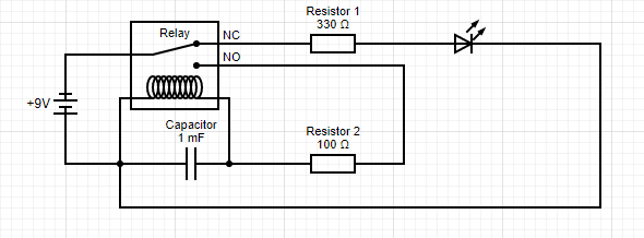
Fig 3: A Blink Circuit Using a Relay
Application of power to the circuit prompts the battery to commence charging the Capacitor via the 100-ohm resistor. Shortly, the relay pulls the contact to complete the circuit, thus switching the LED.
At the moment, the capacitor charges fully. Hence, it will the relay’s contact in the position shortly before the capacitor discharges. After discharging, the relay returns to its original position, disconnecting the contact, and the LED goes off.
The time cycle repeats itself continuously, causing a steady blinking of the LED.
Blinking Circuit Using Transistors

Fig 4: Christmas Tree with Blink LEDs
Using a Single Transistor
The transistor will function as a switch as we operate at its active and cut-off regions.
Components required
- An NPN transistor
- Two 220-Ohm Single resistors
- A 9v battery
- A LED
Circuit Diagram
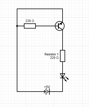
Fig 5: A Blink Circuit using a single Relay
Circuit Explanation
As current flow through the base of the transistor, the collector current moves to the emitter end. Consequently, it will light the LED. Notably, the base current must be higher than the transistor’s minimum requirement.
Next, they’ll be a 0.7V voltage drop across the LED, prompting it to emit light.

Using Two Transistors
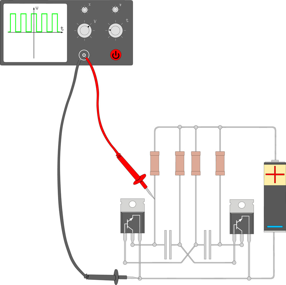
Fig 6: Electric circuit of astable multivibrator
You can create an Astable Multivibrator circuit using two transistors as an advanced version of the above circuit.
Necessary Components
- Four resistors with resistor values of 470 Ohm, 47K, 47k, and 470 Ohms.
- A 9V battery
- Two electrolytic capacitors, each ten µF
- Two NPN transistors
- Two LEDs
Circuit Explanation
In this circuit design, there are two capacitors. When one capacitor charges, the other discharges. In turn, this turns the transistors on and off.
Hence, when one of the transistors is on, it will allow the passage of current, thus switching the associated LED. Similarly, the converse happens to the other transistor for each duty cycle.
Therefore, from this circuit, the LED will switch on in sequence.
Blinking Circuit with Microcontroller

Fig 7: Blink LEDs
Controlling LEDs with a microcontroller such as ATMEGA8535 is an effective way of realizing unique blinking patterns. For instance, you make a blinking circuit comprising 8 LEDs. But you’ll need to connect a 220-ohm resistor between the LED and the microcontroller pins.
In our experiment, we’ll connect the 8 LEDs to ATMEGA8535 pins 33 to 40. Also, on the microcontroller, we have the output pin via which we deliver a 5V voltage to the LEDs we want to switch.
In such a setting, we need a biner code programming system. Hence, given that![]() it will feature eight output ports, our basic biner code will look as follows:
it will feature eight output ports, our basic biner code will look as follows:

Note that from the code, we can change the value of x to 0 or 1. When the value of x is 0, the LED will remain off. But when x is 1, the LED will go on. Thus, by manipulating the code, you can control how the eight LEDs switch on and off using the microcontroller code.
Microcontroller Blinking Circuit with Transistor
In other cases, we may want to switch on a larger LED than in the above case, thus necessitating the use of more current. Primarily, the microcontroller gives a 5V output voltage.
Hence, we can connect an NPN transistor to an external (5-12)v power supply to boost the power supply voltage. Check out the circuit diagram featuring the newly incorporated transistor.
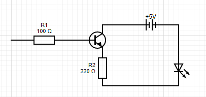
Fig 8: Using an NPN Transistor to connect a Blink LED to an external power supply.
Note that the Resistor R1 in the circuit connects to the microcontroller’s port 40. Meanwhile, the other LEDs connect to the other LEDs in ports 33 to 39, as highlighted in the circuit we covered earlier.
Microcontroller Blinking Circuit with An Inverter
It is a simple LED circuit that needs a few components that include the following:
- A Schmitt Trigger Inverter
- Two Resistors- 470 Ohm and 10K
- A 100 µF capacitor
- LED
- Connecting wires
- Supply Voltage source
Circuit Diagram
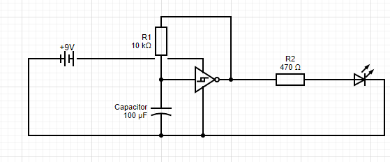
Fig 9: Blink LED with inverter circuit.
Circuit Explanation
An inverter gives an output signal of the opposite input.
From our circuit diagram, the inverter’s output connects to the input via a resistor. Hence, a high input voltage on the input will cause a low output. But, remember that output connects to the input, therefore, rendering the input to go low.
In turn, low input will cause a high output, and the cycle will continuously repeat itself.
A capacitor in the circuit will slow down the inverter’s input. Hence, there will be timeable blinking of the LED.
Also, note that the sizes of Resistor R1 and the Capacitor control the LED blinking frequency.
Conclusion
Above are the five main ways to create a LED blinking circuit. For more on this, contact us, and we’ll respond promptly.


