


On a 480 V packaging line, a single failed component inside an industrial control panel—a power supply, a breaker, an overload relay—can bring production to a grinding halt. Unplanned downtime mounts, and maintenance teams are left chasing symptoms instead of fixing the root cause.
Understanding what each component does, how it interacts with others, and its common failure modes is the key to building and maintaining reliable industrial control systems. This guide breaks down the essential components inside a typical control panel, from power distribution to motor control, to help you diagnose faults faster and build more robust systems.
Contents
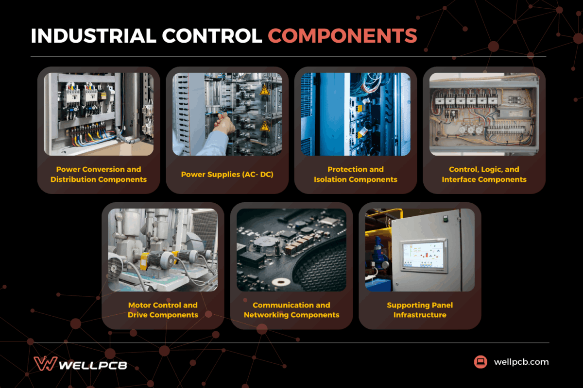
- 1 Power Conversion and Distribution Components
- 2 Power Supplies (AC- DC)
- 3 Protection and Isolation Components
- 4 Control, Logic, and Interface Components
- 5 Motor Control and Drive Components
- 6 Communication and Networking Components
- 7 Supporting Panel Infrastructure
- 8 Putting Industrial Control Components in Context
- 9 Industrial Control Components FAQs
Power Conversion and Distribution Components
Incoming utility or motor control center power feeds conversion equipment that delivers stable voltages to downstream devices. Undersized transformers or poorly applied distribution hardware reduce reliability and limit later expansion.
Transformers
A transformer steps down high-voltage AC power (e.g., 480V) to a lower, usable control voltage (e.g., 120V AC). This allows it to power internal components like contactor coils, relays, and other auxiliary devices that cannot run on the main line voltage.
Inside the enclosure, the transformer commonly feeds:
- Control circuits
- Legacy contactor coils
- Interposing relays
- Auxiliary devices
An undersized unit, often chosen without considering inrush current, will overheat. Incorrect tap settings or wiring can depress output voltage, causing contactor chatter, nuisance trips, or unstable device response.
Power Supplies (AC- DC)
A DIN-rail power supply converts AC line voltage into the regulated 24V DC essential for modern control electronics. It’s the lifeblood for the PLC, I/O modules, HMIs, and communication hardware, making its reliability critical to the entire system.
Common failure symptoms, often caused by undersizing or heat degradation, include random controller resets, unstable sensors under peak load, and flickering HMI screens. These issues often appear intermittently before becoming persistent as the supply fails.
Terminal Blocks and Distribution Hardware
Terminal blocks create clean, serviceable connection points between internal panel wiring and external field devices. They’re fundamental for organized routing, simplified testing, and efficient troubleshooting.
Distribution blocks and busbars split one feed into branch circuits for organized power distribution. Tight terminations limit heat buildup, and clear labels shorten fault tracing.
Feed-through terminals
These are the standard choice for control and power conductors that pass between internal wiring and field devices. They provide a clean, labeled landing point with no built-in protection. This is appropriate where overcurrent protection already exists upstream, but the wrong choice where a branch circuit needs local fusing.
Ground terminals
Ground terminals terminate protective earth conductors on the grounding rail, giving fault current a defined low-impedance return path. Skipping a dedicated ground terminal and improvising an earth connection elsewhere is one of the more common causes of intermittent electrical noise on signal circuits, particularly in panels with mixed power and control wiring.
Fused terminals
Fused terminals combine wire termination with branch-circuit protection in a single component, making them the right choice for low-current loads — instrument loops, solenoid valves, and pilot devices — where a separate fuse holder would add unnecessary wiring complexity. The practical benefit is that a blown fuse in a fused terminal is visible and replaceable without opening the circuit on either side.
Knife-disconnect terminals
These add a hinged disconnect point that lets technicians open a test or signal circuit without removing any landed conductors. On multi-branch panels where fault isolation often means working live near adjacent circuits, a knife-disconnect terminal shortens test time considerably and reduces the risk of disturbing a correctly wired neighbor while chasing a fault on a single channel.
Protection and Isolation Components
Protection devices prevent faults from spreading into connected equipment. When an abnormal current is detected, isolation devices disconnect electrical power for safer service. The main disconnects, breakers, fuses, and overload relays act as coordinated control components during routine isolation and fault recovery.
Main Disconnect Switch
The main disconnect is the primary safety device, completely isolating the entire panel from its power source with a single handle. Typically installed on the line side, it allows for safe, lock-out/tag-out (LOTO) procedures before any service work begins.
Technicians can lock out the supply before touching terminals or feeder conductors during service. Door-mounted handles are common because the operating mechanism remains outside the enclosure, enabling faster shutdown during maintenance or emergencies.
Fused versions add short-circuit protection at the disconnect, but non-fused versions provide isolation only. Door interlocks block access when the switch remains on and reduce accidental exposure during service. Clear labels matter because easy identification supports safer maintenance and more consistent panel design practices.
Circuit Breakers and Fuses
A breaker is a resettable protective device that opens when an overload or short circuit occurs. A fuse uses a sacrificial element that melts under excess current and must be replaced after operation.
Both protect incoming feeders and downstream branches, and some designs add local fuse protection for sensitive process control loads. Proper selectivity keeps upstream protection closed so that a downstream fault clears without shutting the entire line.
Poor sizing can trip a breaker during motor inrush, but repeated fuse failures often point to a more severe fault path through internal components. After a fault, a tripped handle shows breaker operation, but a blown fuse link confirms element operation.
Overload Relays and Motor Protection
Overload relays protect a motor from sustained overcurrent and winding heat, not from instantaneous short-circuit current. In most starters, the relay is in series with the contactor, and both devices support the control machinery during demanding duty cycles.
Correct relay adjustment is an essential component of industrial control because the trip setting must match the motor’s nameplate full-load current. The trip class determines how long the relay holds during acceleration under normal load. The adjustment range then determines whether the device matches the actual operating current in industrial applications.
Reset mode affects recovery behavior within the enclosure and across the broader industrial automation and control system. If the setting is too low, the startup current can trip the relay during conveyor loading. If the setting is too high, heat can build up in the windings before the relay opens.
Control, Logic, and Interface Components
A programmable logic controller (PLC) continuously executes logic from incoming machine signals. Relays adapt field inputs and route control signals to actuators. Local interfaces display diagnostics clearly and accept operator commands to support consistent operator responses during faults.
Programmable Logic Controllers (PLCs)
PLCs are robust industrial controllers used to monitor and control machine inputs and outputs in industrial automation control systems. Inside the enclosure, the central processing unit runs a cyclic scan of field status and executes the logic program.
A dedicated power supply or power module supports the rack, and local or remote input/output modules exchange field signals. Communication ports connect drives or plant networks within the panel.
PLCs sequence conveyors and enforce interlocks across connected machines. PLCs manage alarms and coordinate control operations during line faults. For maintenance, technicians check the diagnostic light-emitting diode status before opening software diagnostics. Fault screens and channel checks then narrow down the likely failed channel or module.
Relays and Interface Modules
A relay is an electrically operated switch that lets a low-current signal operate a separate circuit. In most panels, relays act as control system components between a PLC output and field voltage.
The arrangement provides electrical isolation, accommodates different voltage levels, and shifts contact wear to a replaceable relay rather than the output card. Interposing relays handle signal transfer. Timer relays add on-delay or off-delay functions. Interface modules group multiple relays in one compact assembly for cleaner wiring.
Contactors serve heavier loads, but relays handle lighter switching duties for devices that control valves, solenoids, or beacons. Low coil voltage can cause chatter, and worn contacts can create intermittent output loss inside the control panel.
Human-Machine Interfaces and Local Controls
Human-machine interfaces are touchscreens or industrial PCs that display process status and operating data for operators. Most units display setpoints and trend views to enable faster decision-making.
One alarm screen can present:
- Active faults
- Event history
- Priority state
- Operator response guidance
In larger systems, these alarms support remote monitoring and control. Local pushbuttons handle start and stop at the machine.
Separate reset stations clear latched faults, and selector switches choose auto or manual operation. Pilot lights indicate run or fault status in industrial environments where fast visual feedback is critical.
Interface devices connect through input circuits or relay logic, so clear labels and consistent colors reduce operator error across panel components and related electrical components.
Motor Control and Drive Components
Motor control hardware starts and regulates high-demand drives across production equipment. Here, these industrial control components translate low-power commands into motor power and protect rotating assets. Components such as variable-frequency drives improve efficiency and enable smoother motion.
Contactors and Motor Starters
A contactor is a high-current relay that switches heavy motor loads from a controller or pushbutton circuit. A motor starter adds overload protection, so that the assembly can control operation and interrupts damaging current.
Across-the-line starters are suitable for simple pump duty, while reversing starters change conveyor direction. Reduced-voltage designs lower stress during acceleration in harsh industrial service.
Burned contacts or failed coils can stop an actuator motor or keep the motor energized. Operators may see nuisance trips when overload settings, supply voltage, or field wiring no longer match the actual load.
Motor Drives (VFDs, Soft Starters, Servo Drives)
Variable frequency drives (VFDs) are control panel components that adjust output frequency and voltage to regulate the speed and torque of alternating current motors. Soft starters limit inrush current and mechanical stress by ramping voltage during startup; then the motors run at a fixed speed.
VFDs and soft starters serve different roles in motor circuits, so the comparison below clarifies where each device fits.
| Feature | VFD | Soft Starter |
|---|---|---|
| Motor speed | Adjusts speed during operation | Runs at a fixed speed after startup |
| Startup method | Ramps frequency and voltage | Ramps voltage only during startup |
| System effect | Processes that need speed control | Loads that need reduced inrush current |
| Best use | Supports tighter process control | Reduces mechanical and electrical stress at startup |
Servo drives handle precise position control and speed regulation in motion systems. Drives communicate with controllers through discrete I/O and analog signals in industrial processes.
Alarm trips often point to wiring faults or incorrect settings. Load problems can trigger repeated faults during operation. Network links support the direct exchange of drive status.
Alarms may include:
- Overcurrent
- Overload
- Overheating
- Overvoltage
Communication and Networking Components
Networking forms the connectivity layer across automation solutions inside the panel. Reliable links are as important as stable power in plants that depend on real-time data and remote diagnostics. Ethernet switches and communication interfaces support visibility and continuity.
Ethernet Switches and Networking Hardware
Industrial Ethernet switches are industrial control components that connect controllers to human-machine interfaces (HMIs), drives, and remote I/O via a single control network. Unmanaged switches are plug-and-play devices with no setup.
Managed switches add diagnostics, segmentation, and redundancy support for complex automation. Industrial models are preferred because they tolerate wider temperatures and resist electrical noise. DIN-rail mounting supports stable installation inside the panel.
Damaged cables, incorrect Internet Protocol addresses, or network loops can disrupt communication. Operators may see delayed screen updates or unstable responses until technicians correct the network fault.
Serial, Fieldbus, and Gateway Interfaces
Serial links and fieldbuses support many industrial control system components in active panel designs. Fieldbus includes newer standards such as Foundation Fieldbus and Profibus PA for process communication.
Gateways and protocol converters let legacy devices exchange data with modern controllers and Ethernet networks without replacing installed hardware. Remote I/O racks and fieldbus couplers move inputs and outputs closer to machines, reducing the distance of cabinet wiring and improving installation flexibility. When these interfaces fail, operators may see offline devices, unstable electrical signals, or alarms that appear without a clear mechanical fault.
Supporting Panel Infrastructure
Supporting infrastructure protects industrial control panel components throughout the panel’s lifecycle. Enclosures and layout affect safety and maintenance access. Grounding and thermal control support reliable operation in industrial settings.
Enclosures, Backplates, and Thermal Management
The enclosure protects industrial control components from moisture, dust, and physical damage. Material and rating selection depend on site exposure, so indoor panels often use painted steel, while areas with corrosive conditions may require stainless steel.
The backplate provides the mounting surface for rails, devices, and wiring ducts, all while supporting grounding continuity and heat transfer. Thermal control may use passive airflow, filtered fans, heat exchangers, or dedicated panel cooling.
Early warning signs include discolored industrial control system components, repeated overheating faults, and enclosure surfaces that stay unusually hot during operation.
Grounding, Bonding, and Safety Circuits
Grounding and bonding provide safe fault-current paths while keeping exposed metal parts at the same electrical potential. Inside the enclosure, ground bars, protective earth conductors, and bonding straps connect doors, backplates, and metal hardware.
Safety circuits use relays or safety programmable logic controllers to remove power from contactors or drives when faults appear. Proper grounding protects industrial control panel components during service and abnormal conditions.
A well-built safety circuit enables maintenance access and keeps the machine on a controlled shutdown path when guards open or operators press emergency stops.
Putting Industrial Control Components in Context
Every industrial control panel is a layered system where each component category depends on the one below it. Incoming power passes through conversion hardware – transformers and DIN-rail power supplies – before protection devices filter out fault conditions that would otherwise reach sensitive electronics. Only then does the logic layer, built around PLCs, relays, and HMIs, receive the stable, clean supply it needs to execute control sequences reliably. From there, motor control hardware translates low-power commands into the mechanical output that drives production equipment.
What this means in practice is that a fault anywhere in that chain affects everything downstream. A transformer running on an incorrect tap depresses secondary voltage, which causes contactor chatter, which triggers nuisance trips that operators and maintenance teams spend hours chasing – when the root cause was a configuration error made during commissioning. Panel performance is never just a function of component selection. Wiring quality, termination integrity, correct device sizing, and documented testing all determine whether a panel delivers its intended behavior across its service life.
Wiring quality directly affects signal integrity, fault response, and long-term reliability. Clear component knowledge supports higher plant availability, steadier maintenance planning, and lower expansion risk.
At WellPCB, we specialize in providing build-to-print control panel wiring assemblies for OEM programs. Our process—from controlled wire preparation and verified crimp quality to 100% electrical testing—ensures every production build perfectly matches your design’s intended behavior.
If your next control panel program requires traceable, reliable, and build-ready wiring assemblies, send us your schematics or bill of materials for a free engineering review and quote.
Industrial Control Components FAQs
How often should industrial control panels be inspected and re-torqued?
Inspection intervals depend on load and site conditions. Many plants schedule yearly visual inspections and re-torque checks for standard-duty panels. Facilities often shorten that interval for panels exposed to heat, vibration, or continuous operation.
What documentation should be standard for every industrial control panel?
Every panel should have an up-to-date single-line diagram and detailed schematics. Standard records should include I/O lists, cable schedules, panel layout drawings, and a revision-controlled bill of materials. Many facilities keep a maintenance log and an as-built summary.
How do environmental conditions influence control panel design decisions?
Site conditions affect enclosure selection and internal design. Temperature, moisture, and contamination influence material selection, cooling method, and component derating. Corrosive or washdown areas often require higher-rated enclosures with sealed devices.
Back to Top: Industrial Control Components: What Each Part does in an Industrial Control Panel


