Contents
What is Inside a Breadboard?

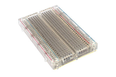
a transparent board with the metal clips
Source: Wikimedia Commons
The breadboard’s internal structure contains rows of miniaturized metal clips. With this configuration, you can quickly push a component’s metal leads into a hole. From there, the pin will clutch that particular lead and hold it in place. Additionally, a backing layer metal strip composed of double-sided tape with protective paper prevents loose connections. You can also attach the breadboard to an object by removing the paper layer.
Even then, some breadboards have a transparent casing, allowing you to see each clip.
Breadboard Diagram
Breadboard diagrams make it easier for beginners to understand where and how each electronic component connects to a circuit. For instance, the chart below contains a pushbutton, switch, LED, resistor, and battery pack.
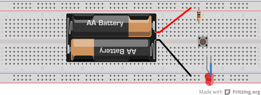
An example of a breadboard diagram with various components.
Source: Wikimedia Commons
How are Breadboards Connected
Wires connect the breadboard in varying colors for easier identification.
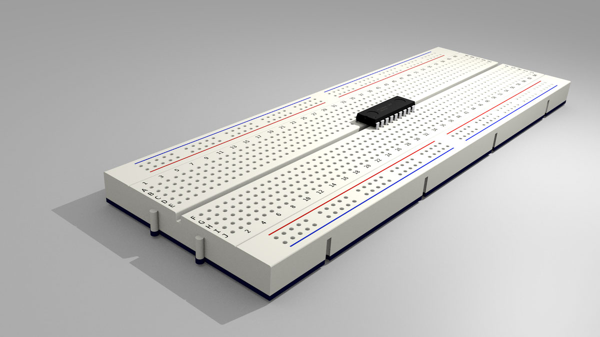
You can integrate an IC into the breadboard holes by placing it on the central gap with its notch facing left.
A wire link should consist of a 0.6mm single-core plastic-coated wire. We recommend purchasing different wire colors for correct connection identification. For example, red references +V (positive rails) while black references 0V (negative rails). It’s also essential to avoid a stranded wire because it crumples as you place them in an individual hole. In addition, broken strands could damage the breadboard.
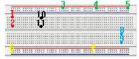
You can connect a power supply to the top and bottom power rails.
Source: Wikimedia Commons
Overall, the power supply connects to the top and bottom rows of holes. In this case, the + references the top rail while 0V references the bottom rail. Meanwhile, the remaining spots connect vertically in columns of five.
Additionally, the board provides separate connection blocks, allowing you to connect an IC pin. You will need to solder components that lack proper leads, including a variable resistor and switch.
Breadboard Circuit Examples
Example one: Simple LED circuit
This section will learn about creating two basic circuits on a breadboard.
Circuit diagram: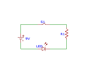
A basic LED circuit diagram.
Electronic component list:
- 9V battery
- LED – 1x
- Resistor – 1x
- Switch – 1x
- Breadboard
- Connecting wire – 1x
- Black wire – 1x
- Red wire – 1x
Follow these steps to create the simple circuit:
Step one:
Source: Wikimedia Commons
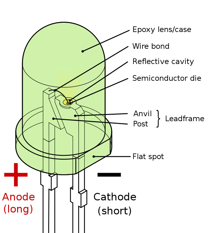
First, you will need to insert the LED and bend its anode lead. Then, connect the LED’s anode to the top rail and the cathode to the main terminal strip.
Step two:
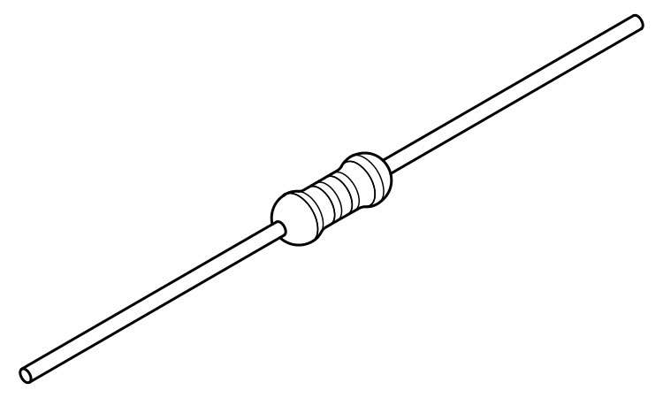
Resistor with connecting leads.
Source: Wikimedia Commons
Next, add the resistor to the breadboard and bend both leads. Afterward, connect one resistor to a hole underneath the LED’s cathode. Then, connect a wire from the other information to the bottom rail.
Step three:
Next, connect the black wire to the battery’s positive terminal and the breadboard’s bottom rail. Afterward, click the red wire to the battery’s negative terminal and the breadboard’s top rail. Lastly, turn on the battery to illuminate the LED.
Example two: Simple LED with 555 IC
Simple LED with 555 IC circuit diagram.
Electronic component list:
- 9V external power supply
- 555 timer IC – 1x
- LED – 1x
- 10k resistor – 1x
- 47k resistor – 1x
- 470 Ohms resistor – 1x
- 100uF capacitor – 1x
- 0.01uF capacitor – 1x
- Breadboard
- Push-button switch – 1x
- Jumper Wire – 1x
- Red wire – 1x
- Black wire – 1x
- Blue wire – 1x
Step one:
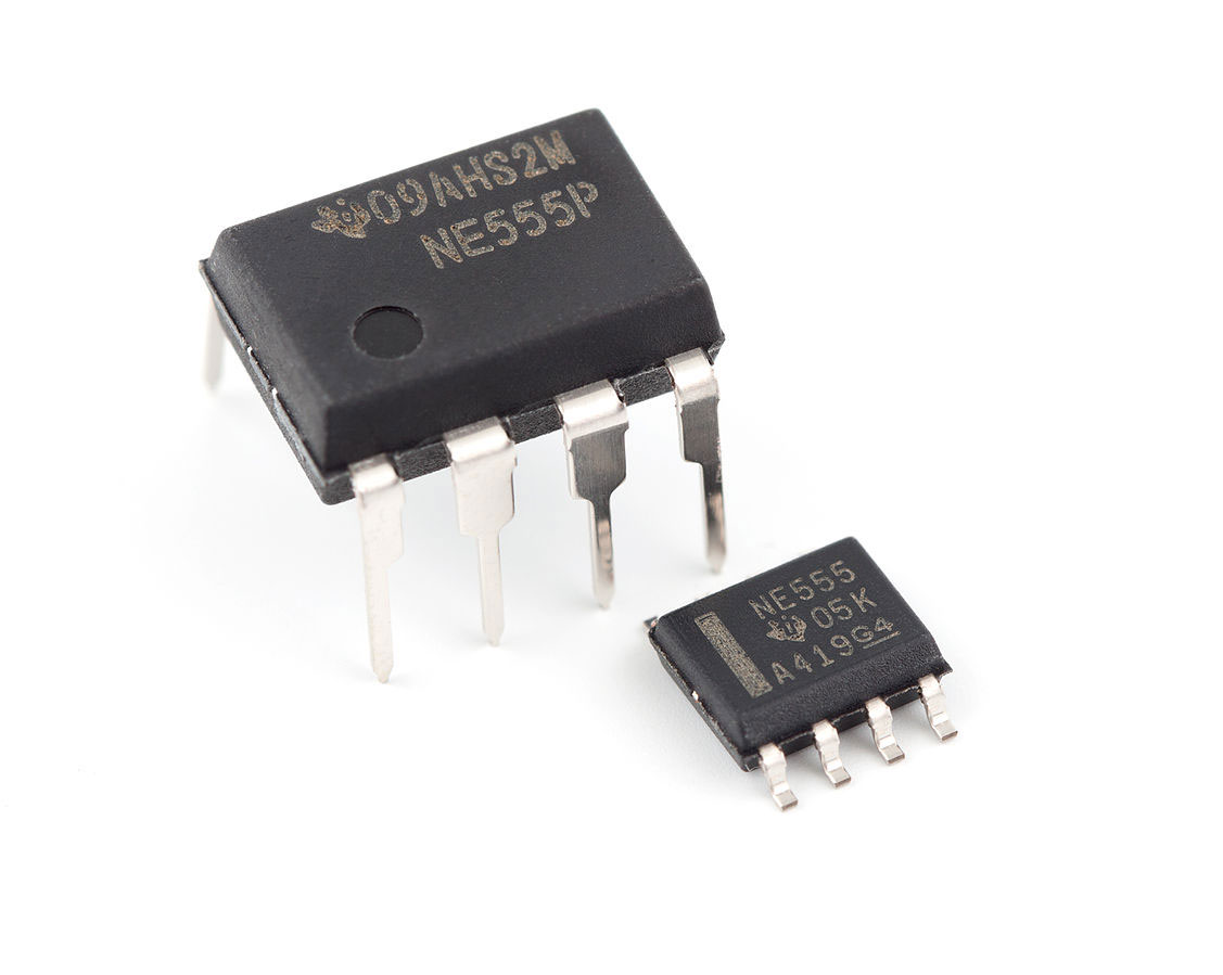
Image showing a 555 IC.
Source: Wikimedia Commons
First, integrate the 555 IC on the middle of the breadboard. Ensure the notch faces the left side. Then, connect a black wire to the bottom rail. Afterward, join a 10k resistor to the top rail (+9V).
Step two:
Connect the switch to the bottom rail. To do this, you will need to solder leads on the button first. Next, add the 470 Ohms resistor to one column of five holes. From there, integrate the LED’s comprehensive information to a spot in that same column and the short lead to the bottom rail.
Step three:
Connect a red wire to the top rail. Then, add the 0.01uF capacitor to the bottom rail. If the leads are too short, you will need to connect a wire link to an unused column of holes. This will then connect to the capacitor.
Step four:
Connect the 100uF capacitor’s positive lead to the 555 IC’s pin six and the opposing end to the bottom power rail. Then, connect a blue wire to the IC 555 pin 7. Afterward, integrate the 47k resistor to the top power rail. Lastly, attach a red wire to the +9V fence.

Common Mistakes
It would help to avoid common mistakes during the circuit creation process.
Source: Wikimedia Commons
You will need to prevent common faults while connecting components to the breadboard. Even then, you can permanently remove the details if a problem occurs. The common mistakes include:
- Components end connect in the wrong row
- Reversed component polarity connection
- Mismatched positive and negative wire connections
- Jumper wires do not connect the board faces
- Improper lead and clips connection with component
- Component leads connect in one row
- Touching leads
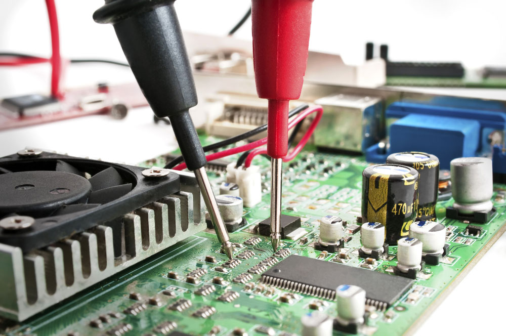
How do I Test my Circuit?
You should test your circuit to ensure it operates correctly.
You can test your circuit using the following methods:
Compare the breadboard diagram with your course to ensure that you connected each component in the correct place.
Verify that the circuit operates as intended. For example, its primary purpose could involve flashing LEDs, generating noise, causing a robot to move, etc.
Connect a battery pack and activate it to turn on your circuit. If smoke arises, then deactivate the power supply right away because that means a short course occurred.
Use the circuit by following instructions. In this case, it may ask you to move around so that a motion sensor can detect movement. However, if you discover the circuit seems inoperable, it will require troubleshooting.
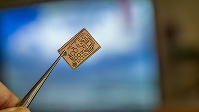
Breadboard vs. PCB
Varying considerations come into play when choosing between a breadboard or PCB.
When designing and implementing electronic circuits, you may wonder if a PCB or breadboard provides an excellent solution. For this reason, we wrote an in-depth guide comparing the two that can help you determine the best approach.
FAQs
Which electronic parts are compatible with breadboards?
A modern breadboard is compatible with batteries, LEDs, diodes, capacitors, transistors, resistors, and ICs.
Do I need any tools to use a breadboard?
Depending on the breadboard type, you will need specific tools. For example, you will need wire cutters for a solderless breadboard and a soldering iron for a solder breadboard.
How are pins connected on breadboards?
To connect a component’s pin, you will need to push it into a hole.
Are breadboard rows connected?
Yes. Each hole connects electrically, meaning that adding the components’ terminals to pairs of holes in one row will form an electrical connection.
What should I do when there isn’t enough space on my breadboard for all the components?
You can purchase a larger breadboard or put breadboards together. In this case, these feature tabs join a second board to the main one.
Summary
Overall, breadboards allow a user to perform temporary circuit project experiments. It features tiny metal clips that grasp onto a component’s lead, securing it in place. From there, you can also connect a power supply and watch the circuit operate as intended. In that case, you can easily remove components as needed, unlike a PCB, which requires soldering. Therefore, you won’t need to worry about making connection mistakes. After all, the breadboard provides purposeful applications for future projects as well.
Do you have any questions regarding a beadboard? Feel free to contact us!


.jpg)
.svg)