Contents
Introduction to Electric Circuits
A closed circuit with different electronic components makes a complete connection. Such components include resistors, capacitors, LEDs, transistors, inductors, and integrated circuits. A resistor application commonly sets the correct current and voltage level. On the other hand, a transistor can amplify or invert your signal.
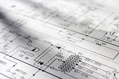
The creation of any object requires designing. Designing circuits is done by first using a schematic diagram which is simply a drawing of the electric path. Manufacturers create circuits with different components, and there are various ways of connecting them. Schematic designs also help you understand electronic circuits better.
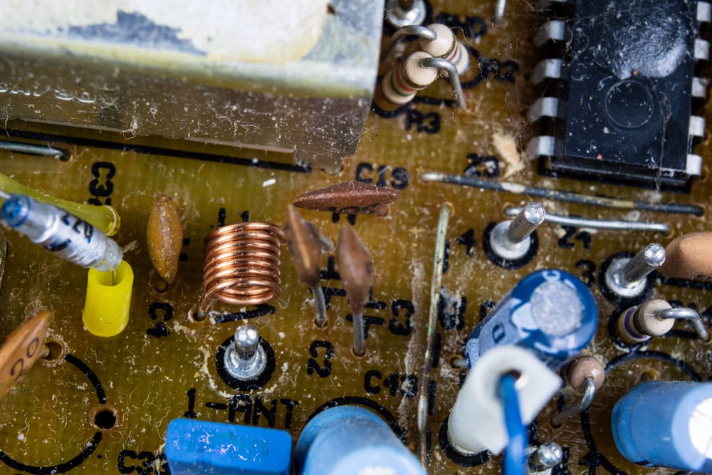
(an electronic circuit board)
Most Common Electrical Circuits for Beginners
Amplifier Circuits
To begin with, devices whose application is to increase the magnitude of the input signal use amplifier circuits. For example, a small sound signal input to a sensor in the radio increases into a more significant output signal relayed onto a loudspeaker. For instance, the change promoted by an amplifier from having an input signal of 1 volt to an output of 50 volts is called Gain.
A good amplifier has a gain that remains constant regardless of the value of the input signal.
A simple electronics project of100-watt subwoofer amplifier has a short circuit that you can create. It is made of transistors only, thus cheap and simple to assemble. The amplifier can allow you to generate up to 100 Watts.
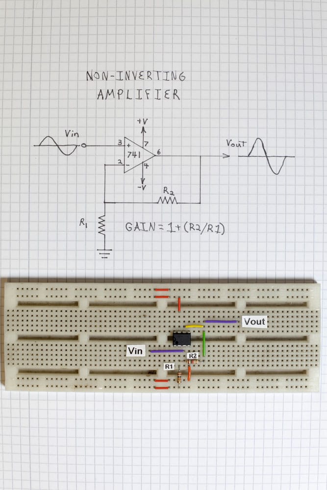
(an image of a non-inverting amplifier)
Alarm Circuits
A rain alarm is a simple circuit for detecting rain. It is helpful for people who harvest rain and warn people with vulnerable items outside that rain is coming.
A simple rain alarm project requires only three components: a rainwater sensor, a 555 timer IC, and a buzzer. The sensor detects rain and sends a signal to the 555 timer, which activates the buzzer that can be an alarm in other instances.
Moreover, a more complex rain alarm circuit requires probes for components. BC548 and BC 558 transistors, 10k and 330k resistors, 01mf capacitor, 3V battery, and speaker.
Rainwater gets in contact with the probe on the circuit, causing current to flow through the circuit. As a result, the Q1 transistors turn on, activating the Q2 transistor (PNP). Also, the conduction of the Q2 transistor allows current to flow through the speaker, generating a buzzer sound.
As long as the probe is in contact with rainwater, the process repeats itself.
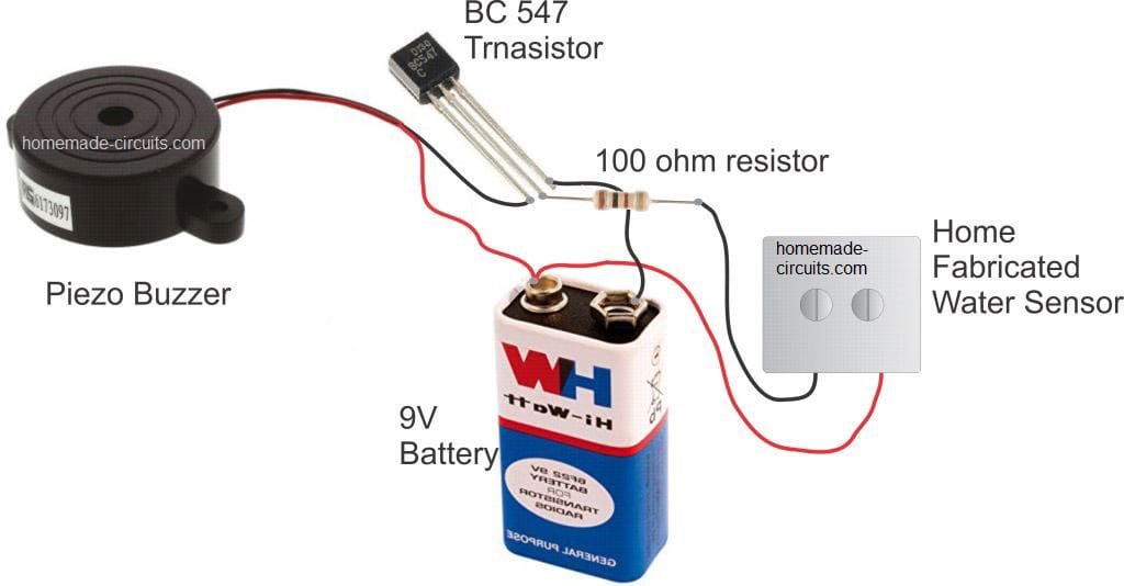
(simple rain sensor alarm circuit)
Lighting Circuits
Lighting circuits are among the most popular electronic paths to be designed, as light is a huge part of our lives. So, you will easily find lighting circuits in automatic LED emergency lights and street light circuits.
A user applies current on an LED with anode +ve and cathode -ve in a DC lighting electric circuit. The path has a bulb to display the output signal and a switch that allows DC input voltage supply to the LED bulb. The bulb also has a negative and positive terminal. The positive terminal of each component is connected, while the negative ends are also connected.
To create an LED emergency light circuit, you will need LEDs, LM317 IC, two transistors, and other common components.
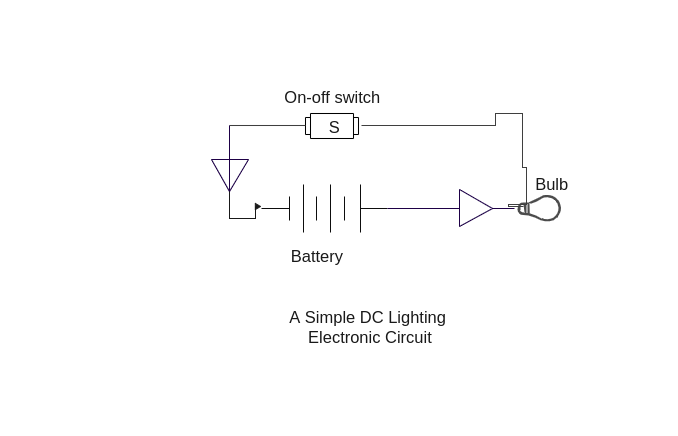
A DC lighting circuit schematic
Charging circuit
Charging circuits commonly appear in lead-acid batteries. For instance, you can easily create a battery charging circuit with a BC148 transistor, SCR, and other basic components. It can charge 12-volt Lead-Acid car batteries of 30-40AH capacity.
(a picture of charging, unforced discharging of RC circuit for Wikibooks circuit theory)
Source https://upload.wikimedia.org/wikipedia/commons/6/6e/Example30b.png
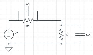
Inverter or Converter Circuit
Engineers use inverter electric circuits to convert the DC power to AC voltages. In fact, the basic principle is to use a DC input to create oscillations that pass through the transformer by amplifying the current. An increase in the original voltage leads to a higher voltage depending on the number of primary and secondary coil turns.
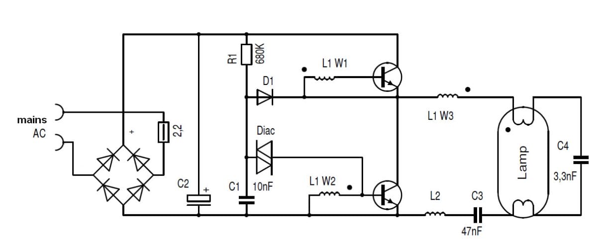
(an image of a current resonance inverter for a Fluorescent Lamp: simplified circuit)
Source: Wikimedia
Controller circuits
Controller circuits are unique as they control the operation of different and separate power circuits. For example, a 1000 horsepower motor connected to a high voltage electrical supply of 2,400 volts driving a water pump.
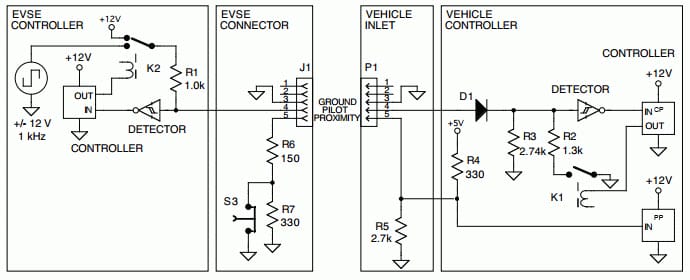
( a picture of a signaling controller circuit)
Source: Wikimedia
Temperature monitor
Also known as a thermistor, a temperature monitor is used by comparing the voltage drop of a “cold” diode (T1) with the base-emitter voltage of a “warm” transistor (T2). Accordingly, transistors should be in physical contact with the heat source, like the heatsink of the power transistors. The effective functioning of the circuit depends on the base terminal of the T1 transistor.
Portable devices and burglar alarm systems use temperature monitor circuits. A temperature monitor circuit board uses an LED. It indicates when the LED battery voltage falls below 9 volts. When the voltage is above 9 volts, the voltage on base-emitter terminals remains the same, keeping both transistors and LED off.
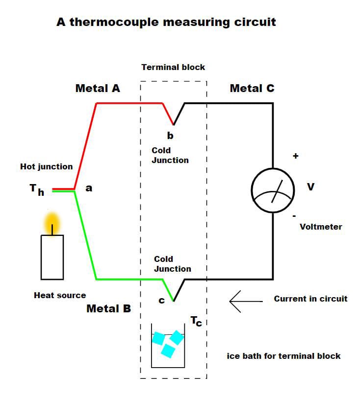
(an image of a thermocouple measuring circuit with a heat source, cold junction, and voltmeter)
Source: Wikimedia
Touch Sensor Circuit
Manufacturers use touch sensors to detect touch, force, or pressure. The circuit captures physical touch or pressure on the device; hence, users can use it to identify their environment in terms of proximity.
A resistor and light-emitting diode are the components used for building the circuit.
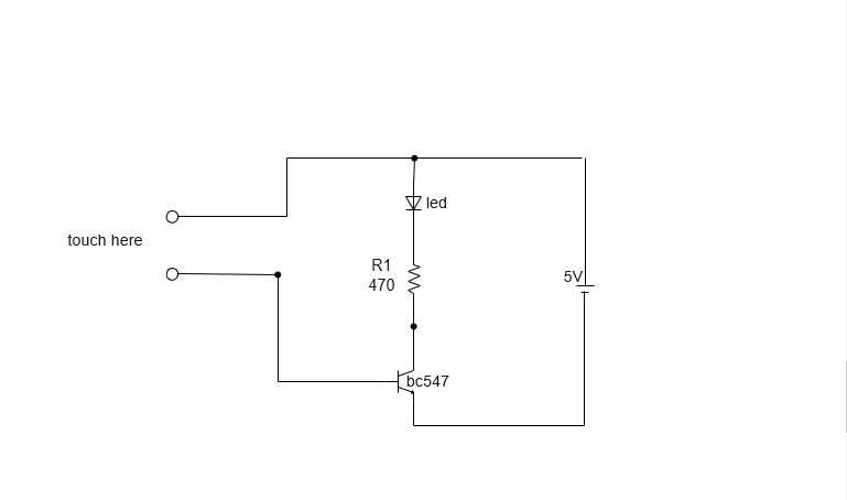
A diagram of a touch sensor circuit
Multimeter Circuit
A multimeter measures the voltage, resistance, and current using a galvanometer connected to the path with a resistor. Probes are connected to the multimeter circuit to measure the passing voltage. Therefore, you use multimeter circuits to measure the DC and AC parameters, and a good application of a multimeter circuit is in continuously winding motors.
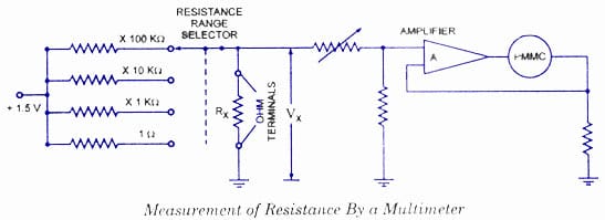
(an image of a multimeter circuit)
Source: Wikimedia
Electronic eye
An electric eye is a great replacement for calling bells. You can use electronic eye circuits to monitor people at your home or office entrance. If an unauthorized person tries to open the door, their shadow will fall on the LDR, causing the circuit to activate. Hence, the alarm rings, alerting the user.
It is a great security system connected to the door or gate with an LDR
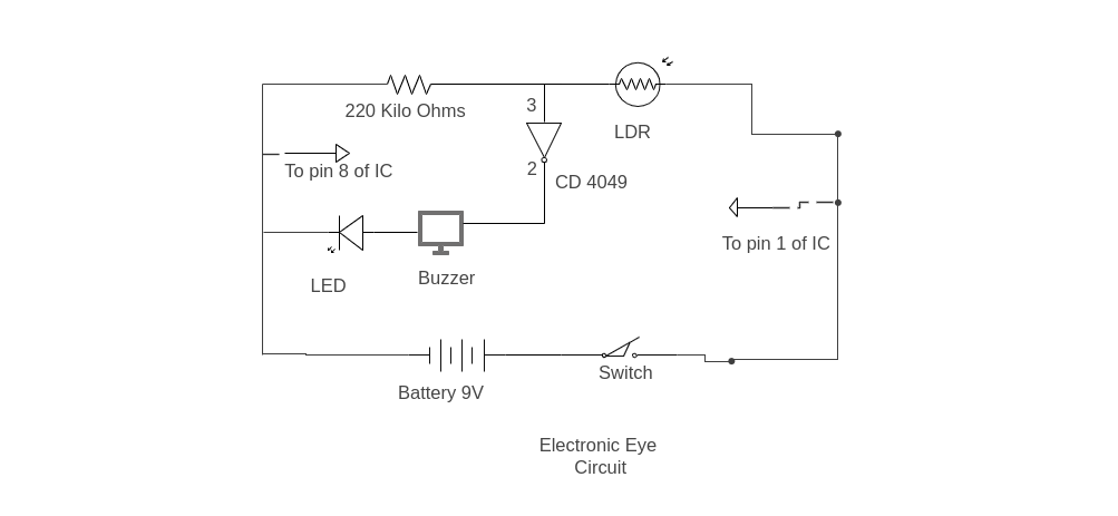
Electronic Eye circuit diagram
Summary
To sum up, this article has provided you with primary and sufficient knowledge regarding circuits and basic electronics concepts. They are an essential part of our day-to-day appliances, and so, we must understand how they operate.
Contact us if you have any questions about circuits or building circuits.


