
The Colpitts oscillator is a linear oscillator and just one among many LC oscillators. Importantly, this oscillator uses the functioning unity of capacitors(C) and inductors(L), thus the name LC oscillator.
This article will discuss the Colpitts oscillator, its advantages, applications, etc. Also, it will help you learn and figure out the right Colpitts oscillator connections for your needs!
Contents
1. What is a Colpitts oscillator?
A Colpitts is an electronic oscillator. Importantly, this oscillator uses inductors and capacitors, which contribute to an LC circuit.
The functioning of this oscillator involves the use of transistors, op-amps, Field Effect Transistors, and valves. Also, it is an electric harmonic oscillator with lots of applications and advantages.
The design of this particular oscillator is similar to that of a Hartley oscillator. However, the distinguishing factor is that the Colpitts oscillator contains a tank circuit while a Hartley lacks the circuit.
Note;
Notably, there are two oscillators; non-linear oscillators and linear oscillators. Non-linear oscillators produce non-sinusoidal output waveforms(non-linear). Whereas linear oscillators, like the Colpitts oscillator, make linear or sinusoidal waves.

(oscillator technology with a motherboard.)
2. Basic Colpitts oscillator circuit and how it works?
- Colpitts theory
The theory of this oscillator is that it has double capacitors in series connected to the inductors in parallel. Notably, the arrangement of these electrical components forms a resonant tank circuit. The combination of capacitors and inductors makes it a parallel LC resonant circuit. In addition, the values obtained from these capacitors and inductors help determine the oscillation frequency.
The invention of the Colpitts was because of the need to generate high linear oscillation frequency using radio frequencies.
Additional Tip
Since the Colpitts oscillator has similar designs to Hartley, it’s sometimes called the electric dual of the Hartley oscillator. However, the presence of a tank circuit is the only differential feature in the two oscillator designs. Otherwise, the functioning difference is that while Hartley uses tapped inductance, Colpitts uses tapped capacitance.
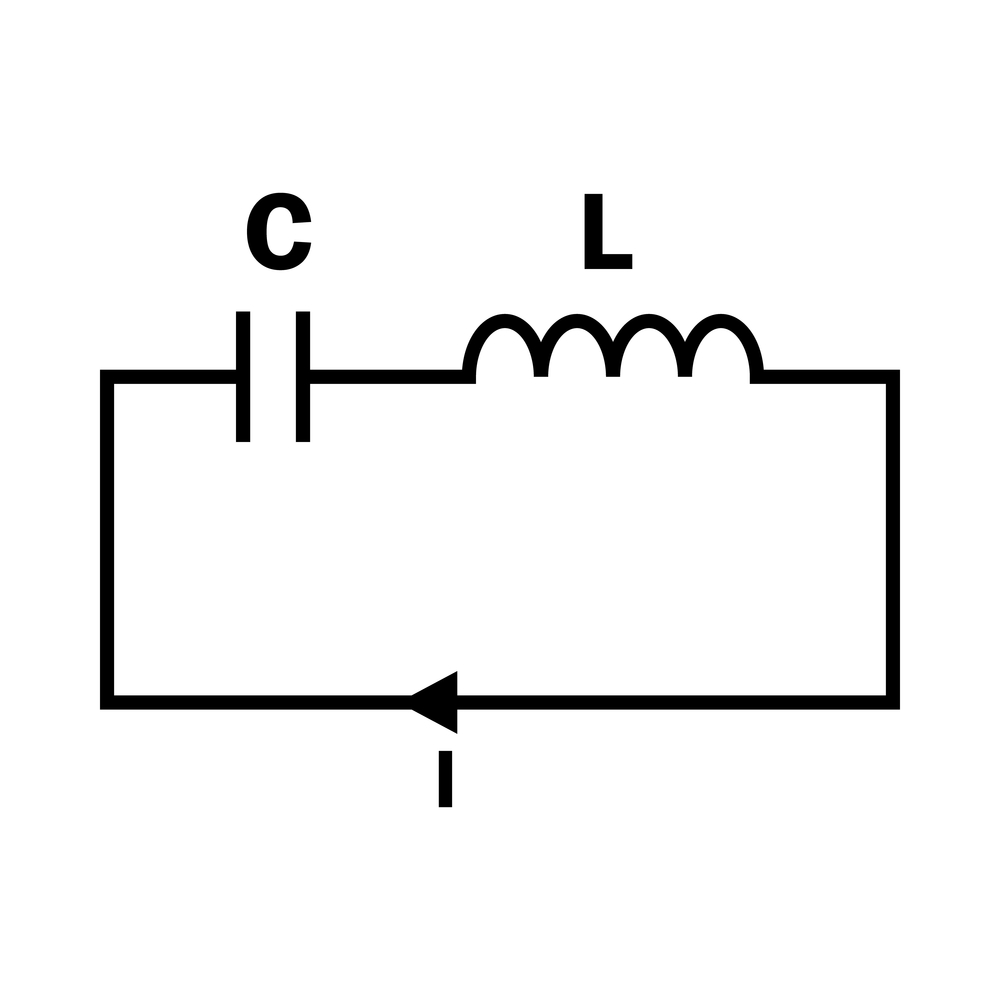
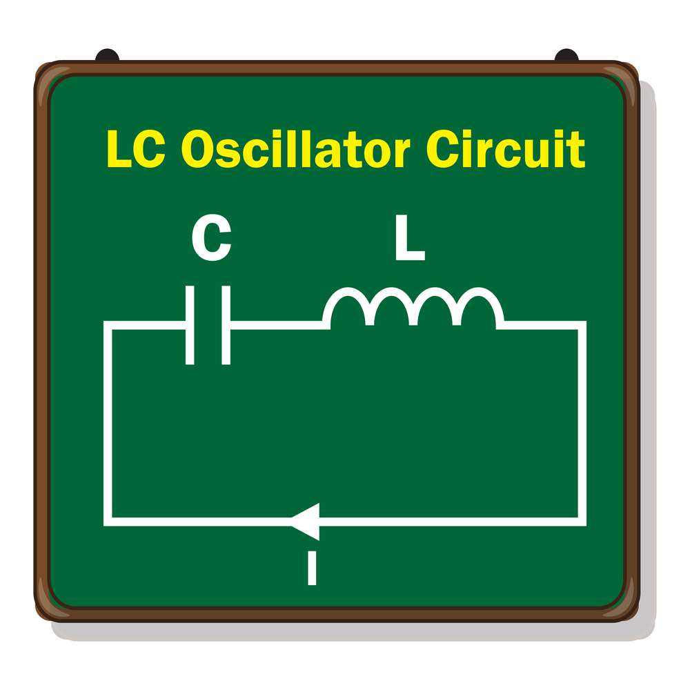
(LC oscillator circuit.)
- Colpitts oscillator circuit

(a Colpitts oscillator circuit diagram)
Just like any oscillator circuit that produces linear waves, the presence of an LC resonant in the circuit is mandatory. However, exceptions are the RC oscillators that don’t need an LC resonant in their course.
Additionally, using a gain device like the Bipolar Junction Transistor, an operational amplifier or Field-Effect Transistor achieves the oscillator function. Importantly, capacitors C1 and C2 create a potential divider. As a result, the frequency stability on Colpitts comes from the tapped capacitance. This tapped capacitance present in the tank circuit is the source of feedback.
However, achieving a stable circuit even in an environment with temperature changes is not easy. Therefore, placing a resistor(Re) in the course is important. The resistor helps keep the circuit stable and prevents it from being damaged.
Also, there is a capacitor(Ce) parallel to the Re. The Ce capacitor acts as a bypass capacitor that generates a low reactive path to the AC amplified signal. In addition, the voltage divider formed by R1 and R2 creates a transistor bias that controls the flow of current.
Notably, from the circuit diagram, an RC coupled amplifier has a common emitter transistor. The output AC coupling capacitor blocks DC. As a result, it gives an AC path from the collector to the tank circuit.
(LC oscillator electrical circuit.)
Colpitts oscillator working
Once the power supply is on, Capacitors C1 and C2 begin to charge. Immediately these capacitors fully charge, they begin to discharge some of their power through inductor L1. Consequently, the discharging process causes the tank circuits to have damped harmonic oscillations.
Again the oscillatory current produces an AC voltage across C1 and C2. During the discharging process, there is a presence of electrostatic energy in the capacitors. This energy will travel in magnetic flux to the inductor, charging the inductor.
Similarly, as the inductors begin to discharge, the capacitors start to charge again. Consequently, this continuous process of charging and discharging generates oscillations. To determine the frequency of these oscillations, use the resonant frequency of the circuit.
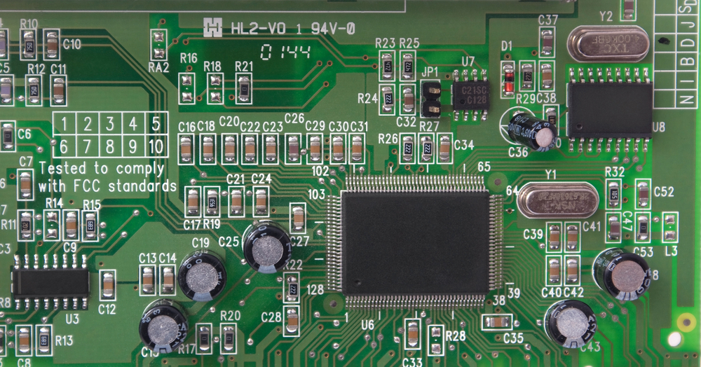
(PCB with mounted oscillators)
The tank circuit mainly works as the energy storage area of the circuit caused by the constant charging and discharging. Also, the formation of the tank electronic circuit comes from the capacitors and inductors’ continuous charging and discharging. This process leads to the parting of the LC network.
Additionally, the Barkhausen stability criterion helps to calculate the continuous undamped oscillations. However, for sustained oscillations, the complete phase shift should be 00 or 3600.
Circuit Formula Calculations
From the circuit, both capacitors become grounded or center-tapped. Thus the feedback voltage, voltage across C2, read 1800, combining the output voltage, which is the voltage across C1. Notably, between the input voltage and output voltage, the common-emitter transistor produces an 1800 phase shift.
Importantly, the resonant frequency is calculated from the formula;
ƒr=1/(2П√(L1*C))
where f is the resonant frequency. C= equivalent capacitance of the C1 + C2, and L1 is the self-inductance of the coil.
And the calculation of C is from the formula
C=(C1*C2)/((C1+C2))
(an oscillator inside a joystick motherboard.)
3. Colpitts oscillator diagram
- Using an op-amp
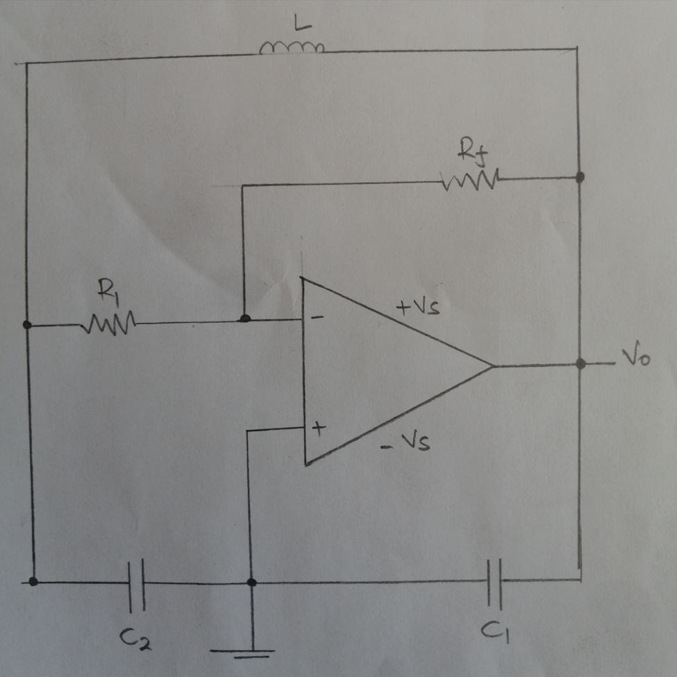
(a Colpitts oscillator using an op-amp.)
The arrangement of an op-amp is in an inverting mode where R1 is the input resistor, and RF is the feedback resistor. Notably, the RF and R1 individual setting of the op-amp oscillator gain has great advantages. Importantly, the equation A = -Rf/R1 calculates the gain of an inverting amplifier.
However, remember that important elements like the coupling capacitors and tank circuit do not affect the op-amp amplifier gain. But, in transistor-based versions, every component affects the gain, especially the tank electronic circuit.
Note that the frequency equation, working principle, and operational theory of an op-amp oscillator are the same as the transistor versions.

4. Colpitts oscillator applications
- First, the oscillator can generate a high-frequency sinusoidal output signal.
- Secondly, the Colpitts oscillator can assist in mobile and radio developments.
- Third, use it in applications that require changing a wide range of frequencies.
- Also, it perfectly works in applications involving frequent high and low-temperature changes.
- Lastly, Colpitts works well in setups where undamped and continuous oscillations are necessary.
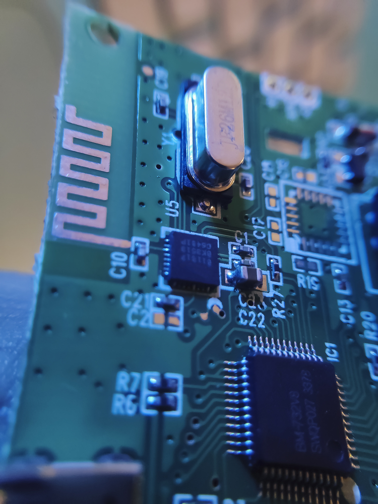
(a photo of an oscillator crystal.)
5. Advantages
- A Colpitts produces linear waves with a high frequency of oscillation.
- The oscillator device can handle low and high temperatures.
- Also, if you use variable capacitors, you can achieve a varied frequency.
- It offers many components to use in a Colpitts oscillator circuit.
- Additionally, Colpitts has a very stable oscillation frequency.
- The output’s oscillation amplitude stays the same if the device is in a constant frequency range.
(several oscillator crystals.)
Summary
Colpitts oscillators provide excellent characteristics that make them an easy-to-use, reliable electronic component. If you’re interested in learning more about your related oscillator projects, contact us! Our team is always happy to answer any questions from you.


