Contents
What is a Constant Current Source?
Generally, a constant current source is a power generator source giving off high internal resistance compared to the load resistance it gives power.
Therefore, it can provide a continuous current to a varying load resistance, sometimes on a wide range, because of its high internal resistance.
Often, it is beneficial in circuits with no fluctuations and a stable current supply.

A graph showing the current from a constant current source
You can note that despite the changes in resistance or voltage, the wind is constant.
How Does A Constant Current Source Work?
The power source uses current division rules in its operation. That is to say, there’s a low load resistance and a high load resistance.
So, the current flows from the path of least resistance, i.e., from the high internal resistance to the current source load resistance.
Below is a diagrammatic explanation;
In our first diagram, the current source generates approximately 40mA (from the total current).
Using the current division rule, most 40mA current follows the least resistant path, which is the 5KΩ resistor. Contrarily, the 10mA current follows the path of larger resistance, 15KΩ.

Current divider circuit – first diagram
In our second diagram, we have increased the resistance dissimilarities between the two resistors to increase the current division intensity.
Since we have the resistors at 49KΩ and 1KΩ, most of the current flow through 1KΩ. 49KΩ resistor will receive little current because of its great resistance.
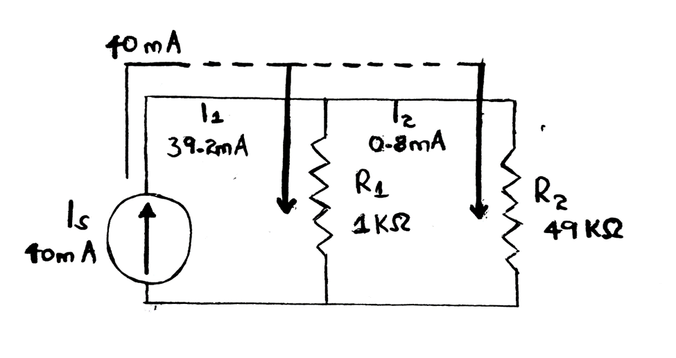
Current divider circuit – second diagram
What if we increase the resistance or have it at an infinity level?

An ideal current device/source circuit
There is a load current of 8Ω and an infinite resistance from the above diagram. Hence, the 8Ω resistor will receive the most current because it has the least resistant pathway. At the same time, the current escapes from the infinite internal resistance load since it has great resistance.
Constant Current Source Circuit
We’ll learn a few electronic circuits that work perfectly on constant currents.
Simple resistor current source circuit
A simple current source circuit only has a resistor. Often, the output current almost becomes independent of the load when the voltage where you need current is lower than the source voltage.
Furthermore, your resistors should have an infinite resistance and the voltage source an infinite voltage to get a perfect constant current source. However, in a practical application, the resistance and voltage should result in almost enough constant over the load recommended.

A simple resistor current source circuit
Constant current source circuit using transistor
Using a transistor alongside other components like resistors helps get an effective constant current source. Consequently, the current source works since the collector current in your transistor circuit is B times your project’s base current.
A circuit diagram showing a single transistor active current source
Providing sufficient voltage to drive the current through the collector’s load device guarantees a functioning independent of the collector voltage.
Simple stabilized active current source circuit.
You can also change a few electronic components in your basic circuit to add some regulations. Thus, you’ll be able to remove any current fluctuations due to changes in supply voltage.

A circuit diagram showing a transistor active current source using Zener diode
The adjustment involves replacing R2 with a voltage reference diode or Zener diode. Otherwise, its working equation is almost equal to the one in a constant current source circuit. The only difference is that the base voltage is more constant due to the diode.
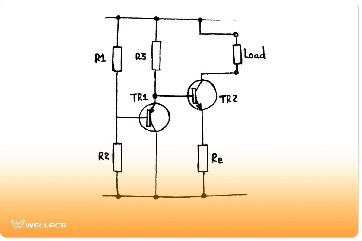
Active current source circuits with good temperature stability
Circuit diagram showing a temperature-compensated transistor active current source.
In the circuit above, we have used both PNP and NPN transistors (Bipolar Junction Transistors) which achieve better inherent temperature stability. Then, if there is a Vbe voltage drop change, TR2 compensates for the changes in TR1.
Note: Here, R3 works as a pull-up resistor for TR1’s collector since the TR2 base cannot source current but can sink it.
You can also include other active devices in your circuit besides transistors, like thermionic valves/vacuum tubes and FETs. However, note that both valves and FETs are not current-driven but rather voltage-driven. Therefore, your circuit and biasing arrangement should cater to the feature.
LM334, LM317, TL431 Constant Current Circuits
We have the LM344 temperature sensor being the most stable source of constant current. It comprises operating at current levels between 1uA and 10mA, determined by the external resistor Reset, and has three terminals. Additionally, besides improving ambient temperature performance, it does not also need added power connection components.
Secondly, we have an LM317 voltage regulator. It is a stable constant current source with three pins that can only create a maximum current of 1Amp.

Circuit diagram of LM317 voltage regulator
Lastly, there is the TL431 device. Besides being a temperature-compensated variable, it also comes in a small TO-92 package. Moreover, you can use it as a voltage reference/source if there is a constant current source.
Note; Before using the current circuits, always measure the output voltage, switch nodes, and input voltage.
What is the Difference Between a Constant Voltage Power Supply and a Constant Current Power Supply?
Power supply devices often supply electrical energy to load through two forms: current sources and constant voltage sources. The power supply circuits involved are constant current power supply and constant voltage power supply.
The two concepts differ from each other.
A constant voltage power supply is a circuit regulating an output voltage to constant current levels. Therefore, despite the load, it will steadily supply a constant voltage without unintended fluctuations (ideal voltage source).
On the other hand, a constant current power supply controls an output current (and not voltage) to constant levels. A perfect example of its application is LED lighting. If the current value fluctuates, the brightness of the LED also changes accordingly.

Blue LED lighting.
Conclusion
Briefly, a constant current source provides a steady current to a load despite variance and changes in load resistance. Thus, they are often ideal for portable devices, electromagnetic fields, solar energy systems, and audio amplification systems.
If you wish to build your constant current circuit, refer to the circuit examples in the post. If you need clarifications or have queries, you can always contact us for assistance.