If you use traditional linear output current power supply often, then you’ll agree that it’s not so efficient. In this case, a buck converter is a better output power option as it lowers input voltage effectively. But, is there more to a DIY buck converter?
Yes, there’s more to the device. First, it has at least two semiconductors. And the semiconductors act like a diode and resistor. But you can replace the diode with a second transistor—which is useful for simultaneous rectification.
Second, the buck converter is highly proficient in performing tasks like changing a computer’s power output supply voltage to lower voltages that devices like the CPU, USB, and DRAM need.
That said, you’ll learn more about the buck converter in this article. In essence, we’ll highlight what it is, how it works, and how you can make one.
Let’s get to it already!
Contents
What is a Buck Converter?
Earlier, we briefly talked about the buck converter. But we’ll talk extensively about the topic here. That said, a buck converter is more like a DC power-to-DC or step-down power converter. Plus, its primary function is to reduce the voltage from the supply (input) to the load (output).
Since the device has at least two semiconductors, as we mentioned, it belongs to a class of SMPS (switched-mode power supply).
Also, aside from the two semiconductors that the device has, it comes with at least one energy storage element.
The energy storage element in question is usually either an inductor, capacitor, or combination. So, if you plan to reduce power transistors voltage ripples, it’s crucial to ensure that the buck converter has filters made of simple average capacitors (or in combination with inductors sometimes) added to the supply-side and load-side filter.
Thus, it’s no surprise that buck converters do an excellent job providing power efficiency as DC-to-DC converters compared to linear power supplies. Plus, it’s worth mentioning that this device is over 90% highly efficient—which boosts their effectiveness for tasks like changing a solar charger or computer’s bulk supply voltage.
How Does a Buck Converter Work?
When it comes to bucking converters, it’s crucial to note that the device’s circuit operation is subject to the conduction state of the MOSFET. In other words, the buck converter works based on its state (off or on).
So, the current in the circuit is zero—if the device is in an off-state or the switch is open. But, if the switch is closed or in an on-state, the current will increase. Also, the inductor will create an opposing voltage across its terminals—in reaction to the change in current.
As a result, the input voltage range will drop, which will oppose the voltage of the source and decrease the net voltage across the load.
With time, the voltage across the inductor and the rate of change of current will reduce. Hence, the voltage at the load will increase. While this happens, the inductor will store energy. So, if the switch opens while the current is still changing, the inductor will experience a voltage drop. Also, the input filter voltage source will be more than the voltage at the load.
If the switch enters the off-state again, the voltage source will leave the circuit
Which causes a decrease in current. When this happens, there will be reduced voltage across the inductor as a result of the decreasing current. Then, the inductor will become a current source.
That said, the buck converter circuit operates in two different modes: continuous and discontinuous. The continuous mode happens when the value of the current passing through the inductor never falls to zero throughout the commutation cycle.
As a result, when the switch closes, the buck chip voltage across the inductor is VL = Vi – Vo. And as long as the voltage drop is almost constant, the current through the inductor will rise linearly.
Also, when the switch opens, the diode will be forward biased. So, the current will decrease and the voltage across the inductor will be VL = -Vo. then, the energy that the inductor L store is:
E = ½ LI2L
Further, the energy in the inductor decreases during the off-state and increases in the on-state. Plus, the inductor L is useful for conducting energy from the input to the output of the converter. The discontinuous mode, on the other hand, happens when the load requires very small energy.
Thus, the current passing through the inductor will fall to zero. When this happens, the output capacitor will discharge in each cycle—which causes higher switching losses.

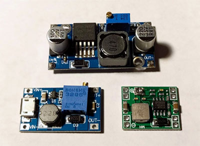
How Do You Make a Simple Buck Converter?
Before you make a simple buck converter, it’s crucial to make reference to a circuit diagram. So, you can make use of the one here.
List of Things Needed
12V input battery
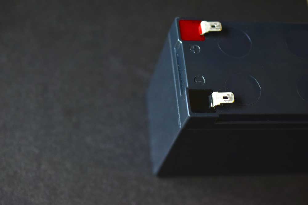
12v Lead battery
Single panel
Resistor (10k,100ohm)
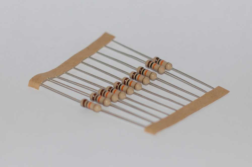
10K Resistor
IRF540N
Motor (load)
Capacitor (100uf)
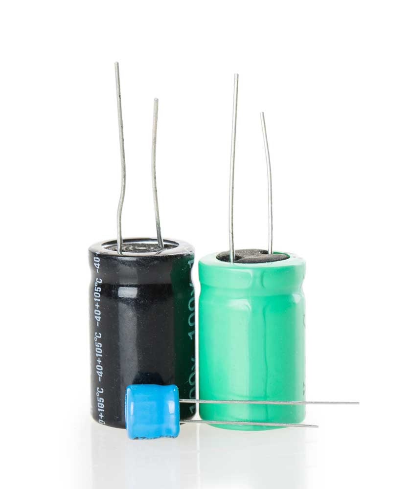
100uf Capacitors
Inductor (100Uh)
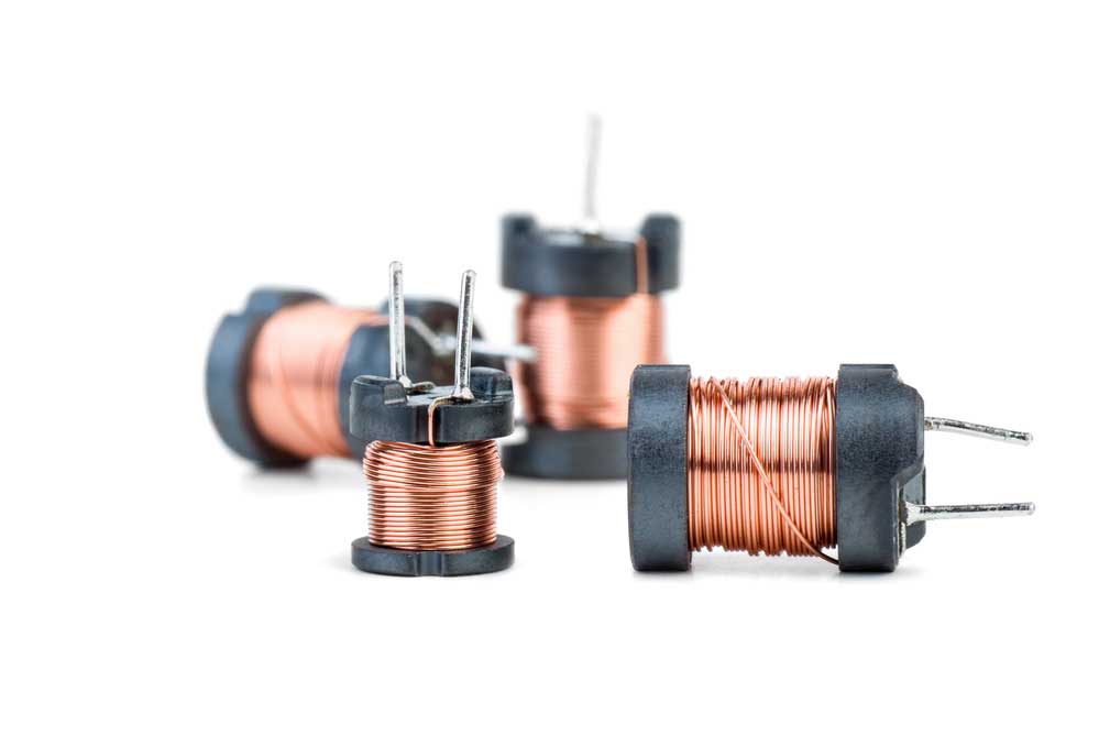
Small 100uh inductors
You can make the buck converter in the following steps:
- Start by linking the end terminals of the potentiometer to the 5v power rail pin. Also, you should connect your ground pin of Arduino UNO respectively while its wiper terminal goes to pin analog electronics pin A1.
- Join PWM pin 6 of Arduino to the bottom of MOSFET.
- Connect the positive terminal of the battery to the drain of MOSFET. And repeat the same thing for the negative to p-terminal of Schottky diode.
- Connect the motor from the p-terminal of the schottky diode in series with the inductor to the source terminal of MOSFET.
- Join the schottky’s diode n-terminal to the source terminal of MOSFET.
- Across the motor, attach the 47uf capacitor.
- Finally, you can link the ground pin of Arduino to the source terminal of MOSFET.
The aim of using the MOSFET is to change the input voltage at a high frequency. Also, it offers less dissipation of heat with a high current. In addition, the inductor plays the role of protecting the MOSFET from high voltage spikes (which is typical of this electronic project).
The Arduino is useful for the MOSFET’s high switching speed. And the function of the Schottky diode is to help complete the loop for the flow of current. So, if there’s no Schottky diode when you switch off the MOSFET, the inductor will release its energy to the motor. Then, it will have little or no effect on load because of the incomplete loop.
The potentiometer is another vital component that offers analog value to the Arduino based on the PWM voltage that the gate terminal of MOSFET receives from the PWM pin 6 of Arduino. With this value, there’s control of the output voltage across the load.
Applications of The Buck Converter
The buck converter is quite useful for some common applications like:
Battery Chargers

Battery Solar charger
It’s typical for most people to want their portable battery pack or smartphone to charge quickly without heating the devices. So, the buck converter is the answer and it’s usually on the inside of the mobile device—since the charging port is a micro USB port.
Power Audio Amplifiers

Power control and audio amplifiers
The power stage of a power audio amplifier is a buck converter. And a good example of this device that uses the buck converter is the class D amplifiers.
Quadcopters
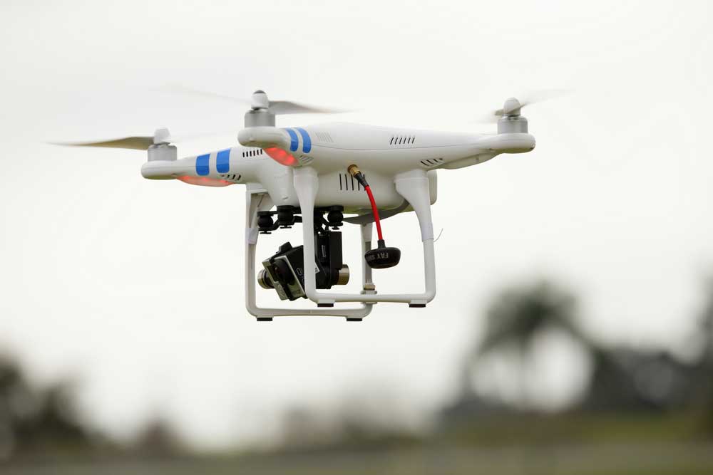
Dji Phantom Quadcopter
Multi-cell lithium battery packs power Quadcopters. And the pack configuration is usually two to six cells in series. Plus, the battery packs produce a range of voltage of about 6V -25V. So, a buck converter helps to reduce the battery voltage to about 5V or 3.3V for the device’s flight controller to use.
You can find the buck converter on the power distribution PCB layout that directs the battery power or the electronic speed controllers.
Bottom Line
The DIY buck converter is the ideal project to hop on if you’re looking for a DC-DC converter that efficiently changes a high voltage to a low voltage. Plus, the device is useful for consumer electronics that require stabilizing the sagging voltage of the battery under load.
What do you think about buck converters? Do you plan to attempt the project? Or do you have questions? Please feel free to contact us.


