About DIY Digital Analog Converter, Translating digitally stored information from an iPod, laptop, or other audio equipment into the analog sound we hear can be a tricky project.
As easy as it sounds, you won’t achieve your desired results without one key component –the DAC.
Despite making your sounds better, a good quality digital-analog converter will allow you to get a better sonic background. Thus, creating a deeper listening scope for your projects.
Here’s the best part.
You don’t have to purchase a DAC; making a DIY DAC (digital-to-analog converter) is inexpensive and relatively easy. Plus, you can do it yourself with a few tools and instruments.
However, if you find this difficult, don’t worry. We’re here for you.
Let’s jump right in.
Contents
- 1 How Does a Digital-Analog Converter Work
- 2 How to Make a Digital-to-Analog Converter
- 2.1 Step 1: Gather Your Materials
- 2.2 Step 2: Install your Components
- 2.3 Step 3: Connect Your XMOS Board
- 2.4 Step 4: Assemble Your Control and Display Board
- 2.5 Step 5: First Testing
- 2.6 Step 6: Choose Your Transformer
- 2.7 Step 7: Build Your Casing
- 2.8 Step 8: Install Your Front Panel
- 2.9 Step 9: Final Assembly
- 2.10 Step 10: Final Set-Up
- 3 Factors that Influence the Conversion Process
- 4 Final Words
How Does a Digital-Analog Converter Work
Before we dive into how a DAC works, let’s discuss what a digital-analog converter is.
The DAC captures digital data from your audio device and turns it into analog audio signals when it comes to electronics. Then. It sends these signals to an amplifier. So, when you listen to digital recordings, what you’re hearing is a converted analog signal.
However, various DACs come with different qualities. For instance, smartphones have basic DACs that work well enough for conversations but not for enjoying your favorite music collection. You would need the DAC of a speaker for that.
Now, we know that a DAC allows us to listen to music stored in digital formats. But, what makes one digital-to-analog converter better than the other?
First of all, you have to understand what happens inside a DAC. Recording engineers convert analog signals into a series of numbers (digital signals). So, if you want to listen to it, you have to convert these bitstreams of numbers back to analog signals.
But, DACs don’t use a consistent timing sequence to convert bitstreams. Thus, it results in what we know as clocking errors. So, when playing these sounds, the errors will show as jitter.
Jitters negatively affect the quality of your playback. In other words, your music won’t sound good enough.
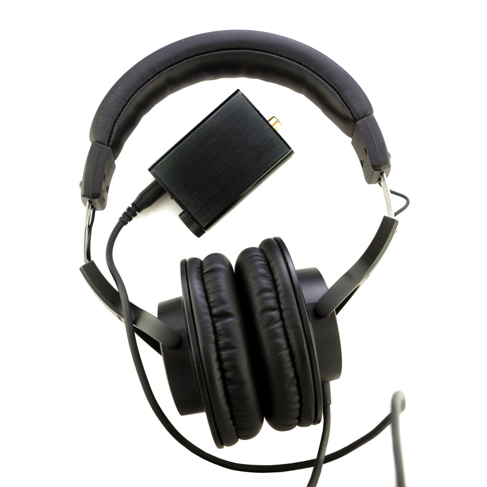
Luckily, outboard DACs (headphones and speakers) have the capabilities to handle these clocking errors. Unlike their counterparts—internal DACs.
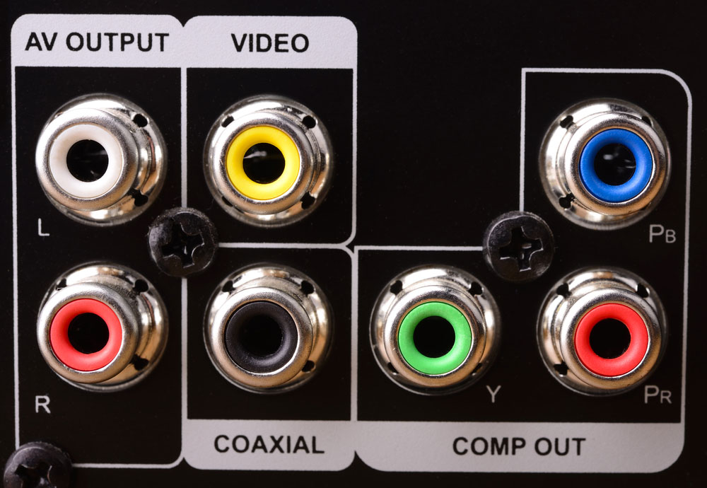
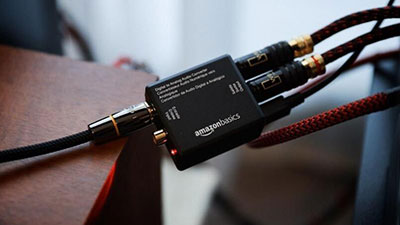
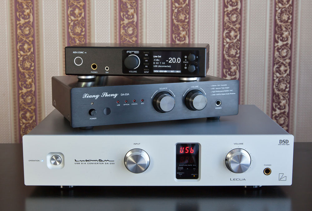
Outboard DAC ports
So, outboard DACs are perfect for every listening setup. Examples of devices with outboard DAC compatibility include desktop and laptop computers, home stereo systems, and smartphones.
Outboard DAC example
How Digital-to-Analog Converters Work
Some years back, we didn’t have DACs to create analog signals. We once used reel tapes and record grooves to create electrical analog signals. However, DACs now allow us to enjoy convenient and portable digital audio.
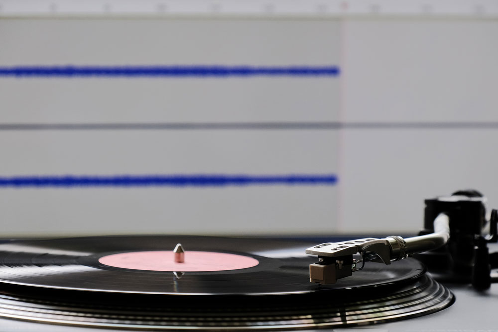
Reel records and record grooves
Here’s how it works:
First, the artist produces a track during the recording process. Microphones capture the voice of the artist and instruments as an analog input signal.
Next, the recording equipment uses analog-to-digital converters (we will discuss this later) to turn analog signals into digital signals. This process allows the easy storage of these signals as a digital audio file.
When you play the digital audio file, the DAC converts the signals back into analog audio signals.
Finally, the DAC transfers the transformed analog output signal to your amplifier. Thus, sending music through your speakers or headphones.
How Analog-to-Digital Converters Work
As mentioned earlier, ADCs play an important role in the process of digital to analog signal conversion. ADCs digital logic circuits like raspberry Pi and Arduinos to transmit in the real world.
Analog signals come from different sensors and sources that measure temperature, sound, movement, sound, or light.
While analog signals provide an unlimited number of different reference voltage values, digital version circuits work with binary signals with only logic states, logic high (1) and logic low (0). So, we need an electronic circuit that can handle this conversion. That’s where the ADC comes in.
So, an ADC captures the analog voltage and generates a digital output code that represents the analog voltage. But, how does it work?
An ADC follows a sequence during conversions. First, it samples the analog signal and quantifies it to determine its resolution. Lastly, it sets the binary value and transfers it as a digital output signal to the system—for reading. The two crucial aspects of this process are the resolution and sampling rate.
How to Make a Digital-to-Analog Converter
Since microcontrollers only read digital signals, various models come with ADC. But, there are few with a DAC. So, we will show you how to make an easy digital-to-analog converter with easy-to-acquire materials. Plus, you can easily expand it to limitless resolution bits.
Without further ado, here are the steps:
Step 1: Gather Your Materials
You can either order your set of materials or gather them yourself. FoYou’lleed a printed circuit board, resistors, capacitors, diodes, and XMOS board.
Step 2: Install your Components
The first things you need to install for this project are your resistors and capacitors on your PCB. Install your 470-ohm resistor, followed by your capacitors. But, you have to install the largest capacitor before installing the others according to the markings on the board.
Also, ensure you solder your quartz resonator. Secondly, install your diodes in one direction—so you don’t make a mistake. Lastly, install the connectors according to the markings on the PCB.
Step 3: Connect Your XMOS Board
If you want your DAC to have both SPDIF and USB inputs, you’ll need to buy a special card (XMOS board). So, once you’ve bought your XMOS card, install it with all the necessary connectors and mounting racks.
Note: these components come with the kit.
If you run into any problems in this step, it might be your capacitor. Try switching the location of the smaller capacitors. That should fix the problem.
Step 4: Assemble Your Control and Display Board
The DAC has various switchable inputs and different operating modes; it requires a control and display board. You can find these components in the kit. Next, follow the instructions on the PCB to install your control and display board. Lastly, connect the wires and display, and your circuit is complete.
Step 5: First Testing
Carry out your first testing on the circuit and make sure everything works fine. If your first check shows everything works fine, you’re good to go.
Step 6: Choose Your Transformer
You’ll need three regulated power supplies for your board: 2×15 volts, 9-12 volts, and 9-12 volts. The 2×15 winding consists of 9-12 volts with a tap from the middle. On the other hand, the two 9-12 volts transformers have independent windings. Since the board’s consumption is deficient, you only need about 5-10 watts.
Step 7: Build Your Casing
Now that you have your supply and circuit ready, next is the housing. You can use the case from a satellite receiver or other equipment that fits your circuit. However, installing the board inside the case may require some mechanical work.
Different casings
If you can’t find any casing for your board, you can buy ready-made versions online—as an alternative.
Step 8: Install Your Front Panel
You might experience minor problems while installing the indicator of the front panel. Plus, this also requires some mechanical work to fix.
Step 9: Final Assembly
Build your power supply with a circuit board, two transformers (-15 +15 volts for the first, and two 12 volts winding for the second). Finally, install everything in your case.
Step 10: Final Set-Up
Place the output for headphones and install any A-class amplifier for the headphones inside the case.
Additionally, if you plan on using your device with a USB connection, you’ll need to download your drivers and install them properly.
Note: you can upgrade your DAC by conducting experiments and replacing capacitors and amplifiers. However, if these upgrades don’t show better results, revert to the original components.

Factors that Influence the Conversion Process
Not all conversions require the same count time. Some may need higher, while others may need lower count times. The typical conversion time is 4.1 ms/ 2 -= 2.05 ms. This could be a good value.
However, the value would produce 2 x 244 = 488, which means 488 conversions on average.
So, a slower clock rate equals fewer conversions per second. Additionally, a converter with a low resolution (fewer number of count stages) will have a higher conversion rate.
One more factor that influences the conversion process is accuracy. The accuracy of the comparator determines the precision of the converter.
Final Words
The digital-to-analog converter is an important component on all audio devices. Most of these devices need to communicate with the real world. Thus, they need to convert digital signals to analog signals.
Additionally, you can use four types of DACs for your projects, including delta-sigma DAC, Binary weighted resistor DAC, segmented DAC, and binary ladder DAC.
That wraps up everything you need to know about digital-to-analog converters. If you have any questions, feel free to contact us. We’ll be happy to help.


