A functional logic probe is one of the handiest tools you can have in your electronics workbench. This simple gadget shows you the logic signal levels of electrical wires. As a result, you are better able to troubleshoot problems in your electronic devices. While logic probes are generally inexpensive, you can also build one in the comfort of your home. Read on to find out how you can save money by making a DIY logic probe.
Contents
What is a Logic Probe?

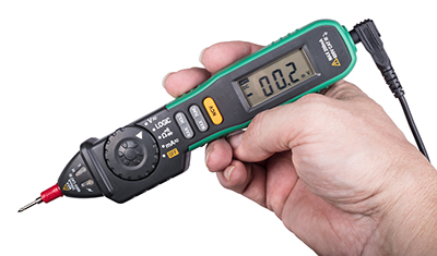
digital tester
The logic probe (digital tester) is used to analyze a digital circuit’s logic level (boolean 0 or 1). Using this gadget, you can determine whether the pin on a chip has a no, low, high, or alternating current. All you need is to observe how the led light(s) behave.
How Does the Logic Probe Work?
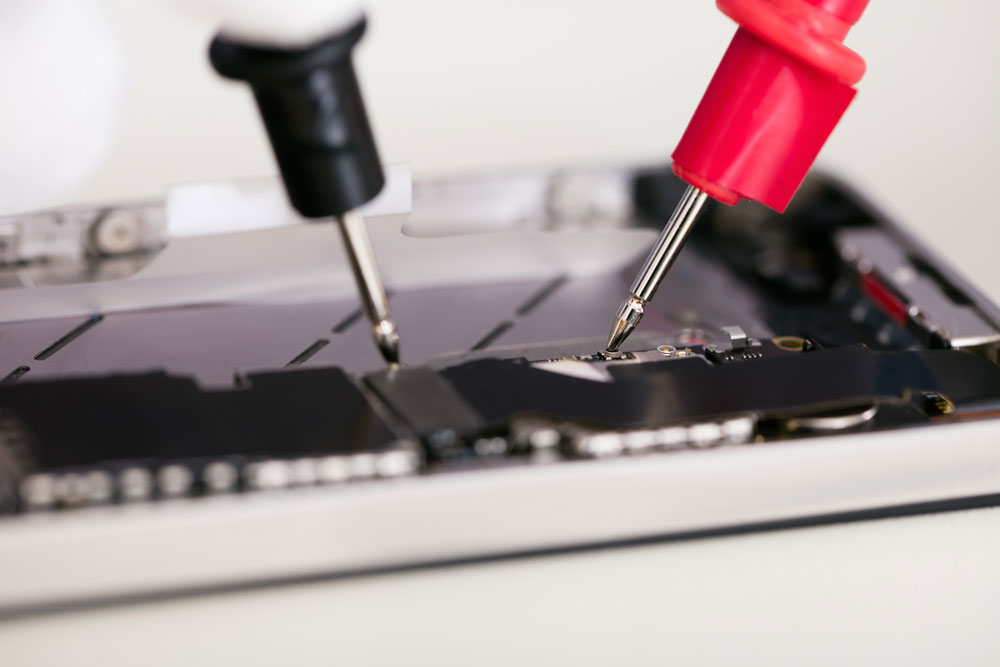
Testing PCBs
A simple logic probe has three connections:
Black Lead with Crocodile Clip
The black clip connects to the negative ground or a common line of the circuit you will be testing.
Red Lead with Crocodile Clip
The red lead of a logic probe connects to the positive supply of the circuit. Most probes can handle between 5V to 9V, and any supply voltage higher than that may damage the probe.
Probe
The probe is a pen-like device with a metallic point used to probe an electronic circuit. When using a probe, always check the voltage supply to ensure it is between 5V to 9V. Next, connect the probe’s ground wire to the ground circuit that you are testing. Once all the connections are in place, probe the circuit to determine its boolean logic.
There are different types of logic probes, and the one in the picture below is one of the most common ones. It features a single light indicator that will change depending on the voltage level.
The indicator usually lights red when it is on. When you place the tip on a PCB device that is not connected, there will be no change in the light. On a device with a high voltage, the brightness of the light increases.
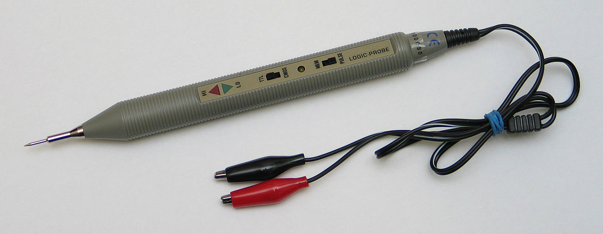
A logic probe with a single LED light indicator.
Source: Wikimedia Common
When you place it on a device with low voltage, the light goes off. When the device has an alternating current, the logic probe indicator blinks.
Another common type of logic probe has LED indicators with different lighting colors. You can have a simple one with a single LED light that goes on only when the voltage through the circuit is low.
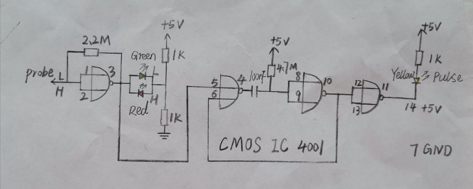
A 3 led light logic probe schematic diagram.
When the voltage is high, the red light glows. In case of voltage drop (below 2.1V), the green light glows. When there is no current passing through the circuit, the yellow light glows.
Some probes have electronic buzzers that emit sound along with light indicators. When the voltage is high, it produces a loud pitch along with the red light. At low voltage, it produces low pitch along with the green light glows.
Be that as it may, they all follow a similar mode of functionality.

Simple Logic Probe Ideas
Below are three simple logic analyzer circuits that you can use to test digital systems. These logic probe circuits support both TTL and CMOS.
1. Simple Logic Probe based on IC-4050

No logic probe is easier to make than this. All you need is ⅙ IC4050 resistance and a LED.
The simplest logic probe to make is this one. I use only ⅙ 4050as and a single LED light, and the LED light only glows up when the input voltage drops or is zero.
If you are looking for a low-cost and easy-to-build logic circuit, then the CMOS 4050 might be the best choice for you. It only needs a 3V electric supply or battery to run.
2. Mini Logic Probe with Transistor Circuit

Very simple logic probe featuring a transistor.
Source: http://www.sowen.com/68/1-logic-probe/
This logic probe design is ideal if you prefer an analyzer with a transistor. You can use this probe to check the voltage levels of a TTL circuit. The mini logic probe kit features two LED lights that show low and high voltage levels.
When the input voltage to the probe is high ( more than 2.1V), Transistor 2N2222 will drive the Red LED with direct bias. In return, the Red LED glows to show the voltage is high.
At low voltage input, the transistor 2N2222 diverts the current through 220 resistors. As a result, the green LED glows.
3. Audio Logic Probe using CD 4011

A simple audio logic probe using CD4011 and 3 LED lights.
This circuit can use a 5V supply. When testing your electrical circuits using this probe, you will hear a beeping sound. The pitch of the beeping tells you the strength of the input signal.
When the logic probe circuit detects low voltage, the green light glows. The beeper produces a low pitch at the same time.
When the logic probe detects high voltage in the circuit, the red light, at the same time, the probe will produce a louder beeping sound.
In the absence of current through the circuit, the yellow light will be on. And the buzzer will not beep.
How to Build a DIY Logic Probe
In this project, you will learn how to build a simple logic probe available right at home.
What You’ll Need
- light-emitting diodes (red and green)
diodes
- jumper wire with mini crocodile clip
- 330 ohm 1/4 watt resistor
- Old push to click ballpoint pen
- 1/8″ brass rod about 1 to 2″ length
Here is a step by step guide on how to build your logic probe:
First, disassemble the pen, remove the ink cartridge, and drill the push button to fit the LED lights.
Then, use a file to grind the brass rod to a pointed tip like you would sharpen a lead pencil.
Drill the cartridge opening to create a snug fit. Next, push the brass rod into the space leaving about 1/4 inch poking out.
Solder a wire onto the brass rod and attach the other end to one leg of the LED. Next, drill a tiny hole for the jumper wire in the lower half of the pen tube. Solder the jumper wire to the other LED.
Insulate the LEDs from their connecting wires using tape.
Test the setup using a battery of between 3V to 9V. To do so, attach the crocodile clip to a known ground of your circuit and touch various points. Check whether the LED lights up. If a component on your simple circuit has a negative or positive voltage, the LED should emit a stable light. By contrast, the LED will blink when applying the probe to the test circuit if the signal oscillates.
Summary
By following the steps discussed here, you can create a functional low-cost probe. Our DIY digital logic probe is low cost but effective in analyzing the simple digital signal. To analyze complex or many signals, I recommend using a logic analyzer instead. Try our step-by-step DIY logic probe guide and make your probe now. Please feel free to contact us for any clarification.


