Solar panels are pretty resourceful as they have endless benefits. And one of them is saving on your energy bill. But, if you want your board to increase its electricity production further, you need a DIY solar tracker.
Solar tracking practically breaks the limitations of static solar panels by moving the system to trail the sun throughout the day. In other words, the solar tracker helps to enhance the points where the panels get solar radiation.
So, what’s the cost of a solar tracker? Well, that’s the downside to this device because the price ranges from $500 to $1000 per panel. But the good news is you can make a DIY solar tracker—from its circuit board to the physical parts.
How? In this article, we’ll talk extensively on how to go about it and highlight the necessary components needed for the project.
Let’s get started.
Contents
What’s a Solar Tracker?
Like we mentioned earlier, a solar tracker is a portable device that helps to position your solar panels to get direct sunlight.
In other words, the solar tracker is responsible for making the panels get as much energy as possible—to boost output. With this in mind, it’s crucial to use components that will increase your panels’ effectiveness.

How Do You Build a Solar Tracker?
The components you need to build a solar tracker include:
- Arduino Micro PLC (1)
- 10k Ohm Photoresistor (2)
- 12VDC Lithium Rechargeable Battery (1)
- 7k Ohm Resistor (2)
- PA-14 mini-linear actuator- 6In- 150lbs force (1)
- Wasp Motor Controller (1)
- Genasun GV-10 12VDC Solar Panel Charge Controller (1)
- Sungold SGM-90W-18 90 Watt Solar Panel (1)
Control System
A solar tracker uses a linear actuator.
And the Arduino microcontroller helps to control the linear actuator with the aid of the Wasp motor controller. So, the linear actuator determines which part of the solar panel gets light. Interestingly, this is possible because the actuator takes reading from the photoresistors.
Consequently, the actuator will modify the solar panel’s position. The goal here is to ensure that the readings from the east and west panels are relatively equal. With this, the solar panel will easily yield maximum power—because the sun will hit it directly.
Motor Controller
In this part of the solar tracker, the Wasp motor controller draws power from the 12V battery.
And it does this to prolong and withdraw the PA-14 mini-linear actuator. Also, we picked the 150lbs force actuator over the 35lbs force version because it takes less current.
Light Sensor
The 10k Ohm photoresistor is quite helpful here as it helps to find the sun’s intensity.
After all, the photoresistor acts similar to the variable resistor that light controls. So, when resistance increases, the light intensity decreases, and vice versa.
Also, you have to use your two sensors on the west and east side of your panel. That way, the solar tracking device will know the location of the sun. Further, proceed to connect one 10k Ohm photoresistor and one 7k Ohm resistor. While you’re at it, ensure that the connection is in series. Then, use the Arduino micro to provide a 5V signal.
Afterward, use the analog input on the Arduino micro to take the voltage reading across the 7k Ohm resistor. Also, when light intensity increases, the 7k Ohm resistor reading will spike up because the circuit acts as a voltage divider.
Source Code
It’s crucial to take note of the code below for your solar tracker. Plus, you can adjust the values accordingly to suit different seasons and regions throughout the year.
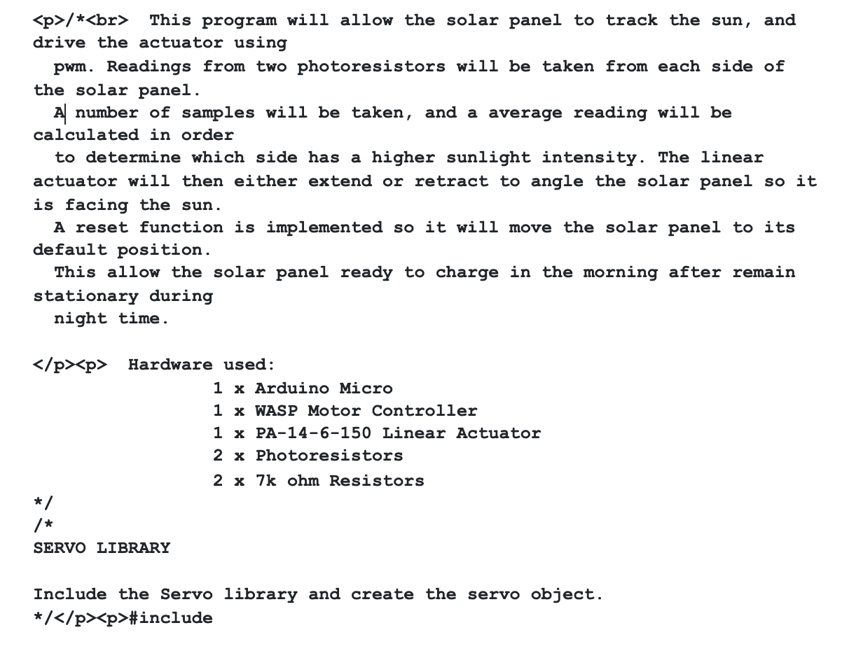

Servo Library
The Servo. h library comes in handy when you need a single line command to enable the Arduino micro to regulate RC servo motors.

Pin Assignments
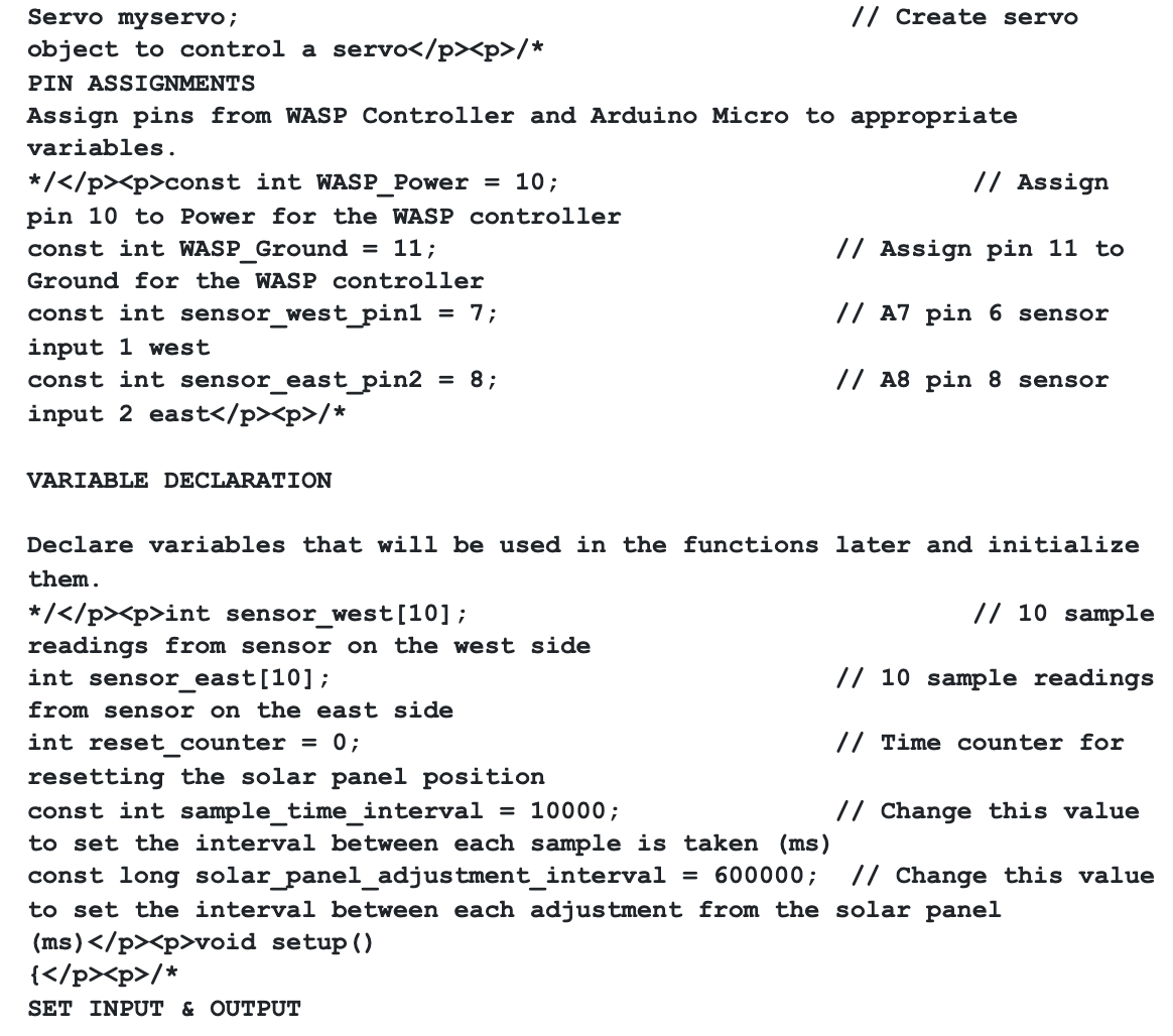
The Arduino micro has a pin 10 and 11 that helps to influence and energize the WASP controller. Also, the Arduino micro’s pins 6 and 8 go to analog 7 and 8. And at this point, the tracker can extract readings from the two light sensors.
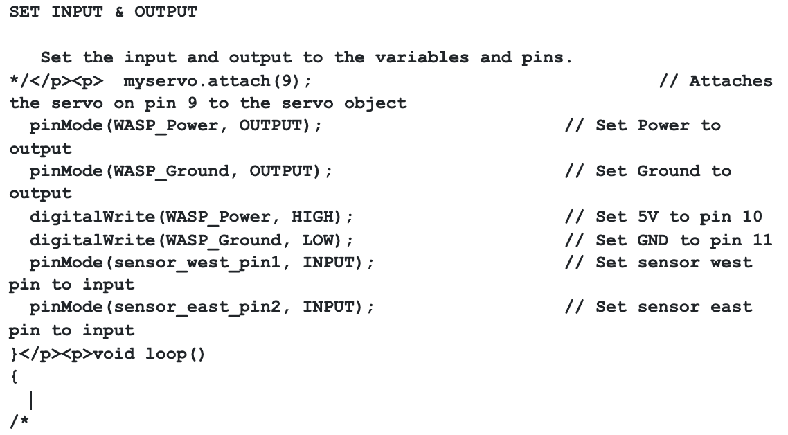
Set Input & Output
If you want the tracker to drive the WASP controller, you can position the WASP_Power and WASP_Ground to output. Also, you can place the sensor_west_pin1 and sensor_east_pin2 to input. With this, the tracker can take readings from the photoresistor light sensors.
Variable Declaration
Variables are useful for storing values that come from the light sensors. Plus, you’ll also find a declaration of the sample time and adjustment interval.
Also, you can tweak the intervals between each angle adjustment the solar panel makes and the gap between each reading. In addition, it’s crucial to note that the previous value will be read every 10 seconds. And the solar panel will adjust its spot every 10 minutes.
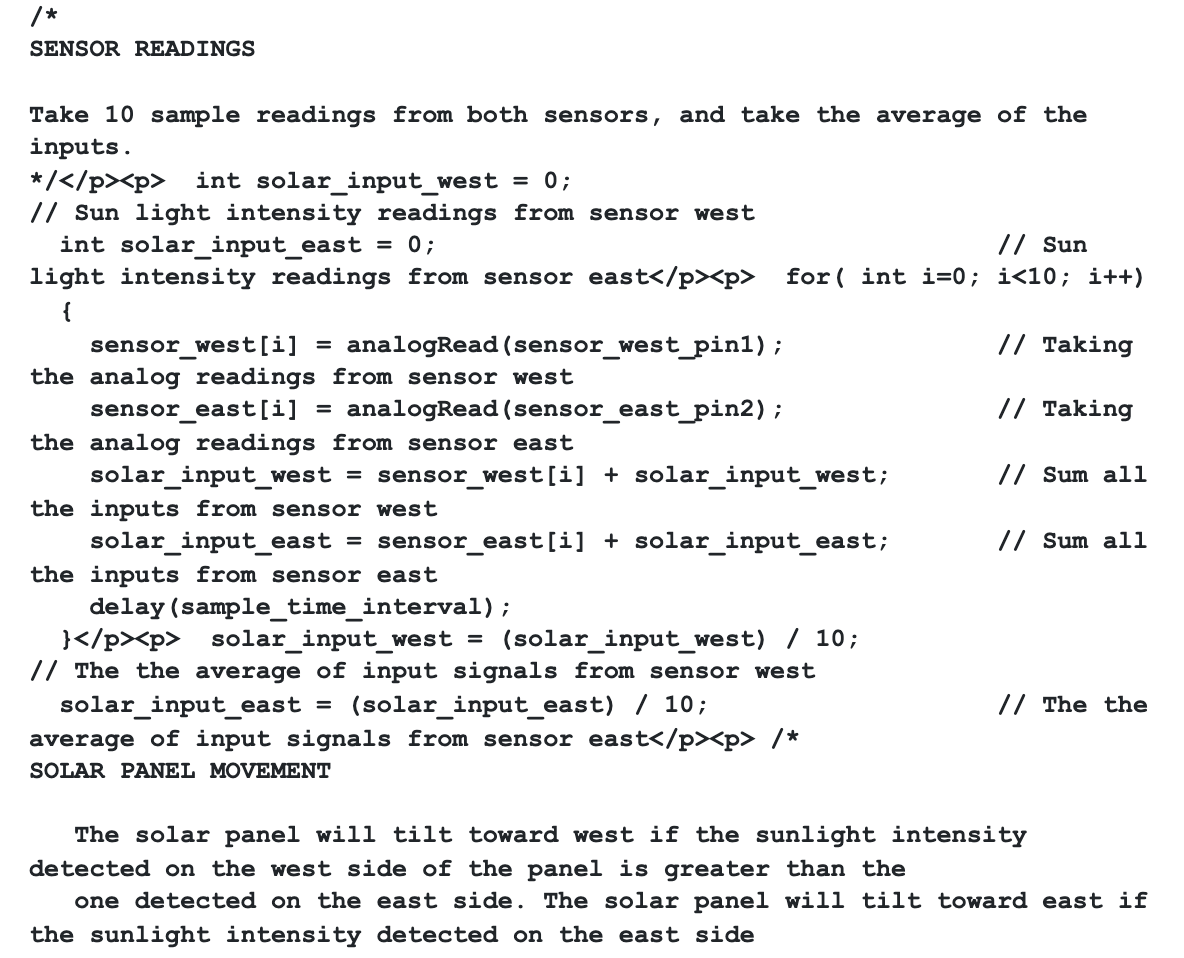
Sensor Readings
When it comes to sensor readings, the program for the tracker will get lessons from 10 samples per 10 seconds. Then, compare the average values of both photoresistors.
Movement of the Solar Panel
The PWM control helps you power the actuator with the Arduino micro. So, you can retract, extend, or halt the actuator at any time, depending on what you set for the PWM.
Also, if you get your sensor readings from the east and west side, the tracker will initiate movement. And this command can cause a retraction, extension, or stationary move. In other words, the signal depends on the variation in sensor reading. Plus, this command will occur at 10 minutes intervals. That way, the panel will get adequate sunlight.
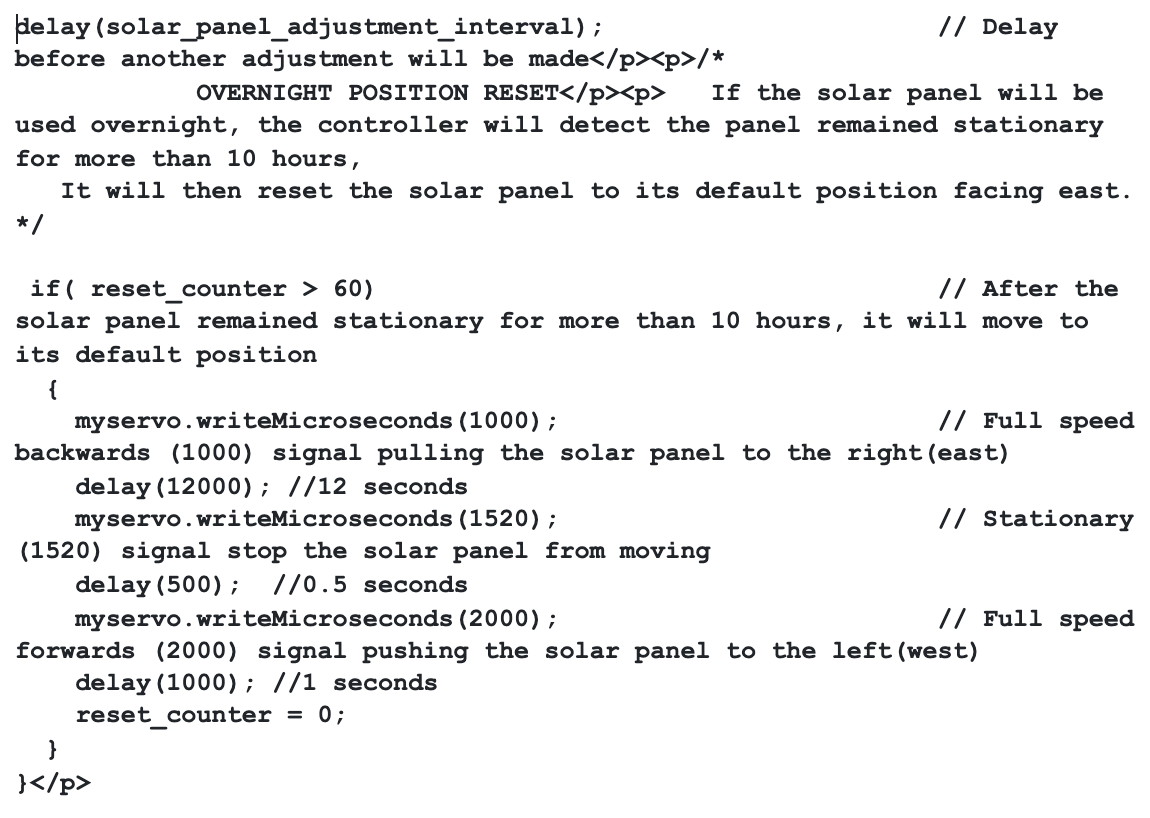
Reset Position
This feature is useful when the solar tracker runs for a long time. That is, it helps the solar tracking device change to default the next day. And a simple counter will do the trick.
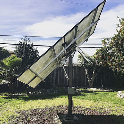
Solar Tracker Frame
To make a sturdy frame, you can use 2×4’s to make a triangle. Or opt for a tripod frame alongside 3D printed parts. With that, you can make the mounts and joints.
Rounding Up
Making a DIY solar tracker is worth your time—especially if you can’t spare the big buck or you’re itching to try a new project.
Plus, it comes with many benefits, like increasing the expense of your photovoltaic solar setup. Also, it saves you a lot on energy bills.
Do you still have questions or concerns about the setup? Please feel free to reach us.


