Are you looking for a way to capture heat signatures during winter but can’t afford any of the commercial thermal cameras? If yes, what you need is a DIY thermal imaging camera.
Making a thermal imaging camera is not as hard as it seems. In truth, the process involves activating your camera sensor’s ability to see infrared light.
The DIY thermal imaging camera is way cheaper than the cheapest seek thermal camera, which costs up to two hundred dollars.
So, in this article, you’ll learn how to build an easy DIY thermal camera with smooth operation and show you how these expert cameras work.
If you also want to learn more about thermal imaging camera circuits, this article is for you.
Contents
DIY Thermal Imaging Camera
The average thermal camera is an expensive device. If you want to rent, it would cost fifty dollars a day. However, you can build a more affordable thermal camera.
In short, it’s possible to convert any digital camera into a thermal camera. Why? Because there are built-in CCD sensors on these cameras that can capture the infrared spectrum of light.
But because prolonged exposure to infrared light could damage the sensor, most manufacturers use an infrared blocking filter to deactivate this feature. Nevertheless, removing the infrared filter from your camera lens can allow you to see the beauty of infrared.
This article will use the MLX90640 thermal camera with a 24 by 32 resolution or 768 pixels for our DIY thermal imaging camera. We’ll also pair the MLX90640 and a Raspberry Pi SBC, allowing it to record temperature maps with reasonably high resolution.
We’ll also use Python to motivate the RPI to produce certain limits. Then, we can position the MLX90640 properly to deliver a thermal camera running a 320 by 240 resolution.
If you want the DIY thermal camera to function while you walk around, you’ll need a way to display the live output from the camera and some battery to keep it running. The best part is that you can also use this DIY thermal camera as a security camera since its resolution is high enough to capture quality images.
Working Principle
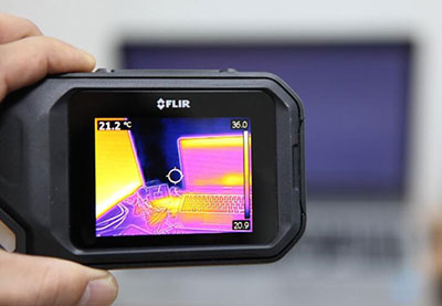
A thermal camera can capture only the infrared region of any object that’s not visible to the human eye. Interestingly, most things can produce infrared energy, which you can also call heat signature. Hence, a thermal camera detects and measures an object’s infrared energy.
Also, the camera converts the infrared data it detects and measures into an electronic image. The electronic image shows the surface temperature of the thing you’re measuring. Thermal cameras also contain optical systems that gather infrared energy onto a special detector chip or sensor array.
In addition, the sensor array houses thousands of detector pixels in a grid style. Here’s the best part. Each pixel on the sensor array detects the infrared energy focused on it and creates a matching electronic signal.
The camera processor then calculates each pixel’s signal and creates a color map showing the temperature. Also, each temperature value has a different color. Finally, the produced matrix of colors moves to the camera’s memory and displays a thermal image of your measured object.
Most thermal cameras come with standard cameras that automatically capture visible light and create standard digital images. When you blend these images, you can easily detect problem areas in your thermal image and match them with the actual area and equipment you’re inspecting.
Components Needed
You need two components to build a DIY thermal camera, including:
- Raspberry Pi 4 Computer
- MLX90640 thermal camera
While the prices for the two components may change depending on where you purchase, the project should cost nothing more than one hundred and fifty dollars.

Steps
Here are the steps you need to follow for building this project:
Step 1: Wiring
First, you need to connect your MLX90640 to your Raspberry Pi. Check out the image below to see how to wire your components.
Also, the Raspberry Pi and MLX90640 use an I2C protocol to communicate. This I2C protocol requires the Pi’s hardware pins five or three (SDA or SCL) to work.
Step 2: Using MLX90640 to Set Your Raspberry Pi
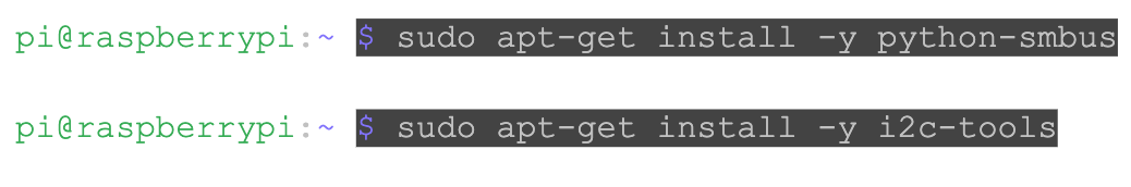
You’ll need the Adafruit library to program the breakout board of MLX90640. Hence, input the following codes on your Raspberry Pi terminal to check if you can visualize the MLX90640’s sensor in Python:

It would help if you also did this; use the following commands:
Use the following commands: also, use the following commands to check if you have I2C enabled:

The command should start the boot file on the RPi. Once it’s open, navigate to the dtparam=i2c_arm=on and ensure that uncomment is not disabled. After enabling your I2C, restart your RPi with the command below:
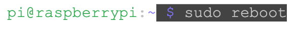
If all your wirings are correct, you can check the I2C port to see if the RPI registers your MLX90640 after rebooting.
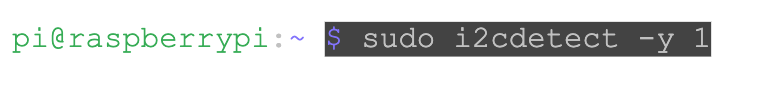
You should get the following results on your terminal:
You’re good to go if you see the number 33 on your terminal. It’s because the I2P address of the MLX90640 is 0x33. However, be sure to confirm this on the MLX90640 datasheet.
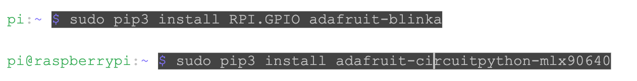
Now, your Raspberry Pi should be able to read the breakout board of MLX90640. But, you’ll need to install some other libraries since you’re working with the Adafruit library. The following commands can help you with that:
Next, you can install Python IDLE (Integrated Development and Learning Environment), but it’s not a required step. However, you can use the following code to install IDLE:

Lastly, open IDLE and try importing your MLX90640 library from Adafruit with the following test code:
The code results above should be a print of the average temperature your MLX90640 reads. Don’t panic If you encounter any refresh rate error while reading your MLX90640.
You can solve the issue by increasing the rate of the I2C device on the RPi. Hence, you’ll need to make some adjustments to the “config.txt” file with the following command:

Move to the section with uncommented ‘dtparam=i2c_arm=on’ and add the following line to increase the I2C’s speed to 1Mbit/s: “i2c_arm_baudrate=1000000”.
Step 3: Visualizing the MLX90640 Real-Time Thermal Camera
There are different ways to visualize your MLX90640’s output while using Python. One of them is “imshow,” which allows you to view any image.
Here’s a simple implementation of the MLX90640 visualization below using imshow in Python:
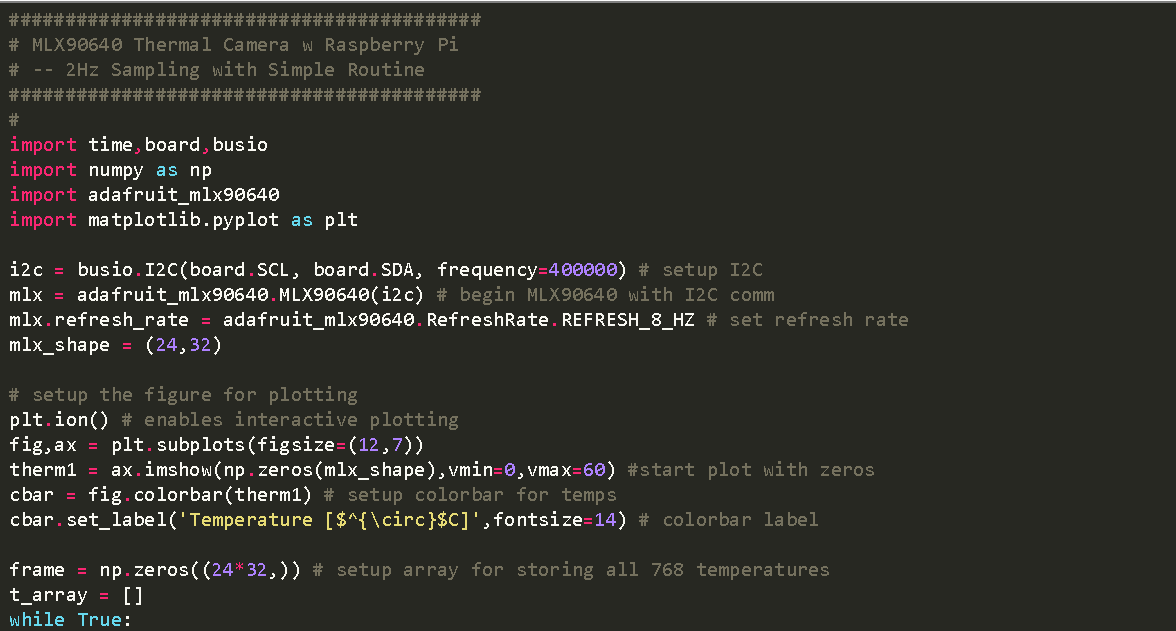
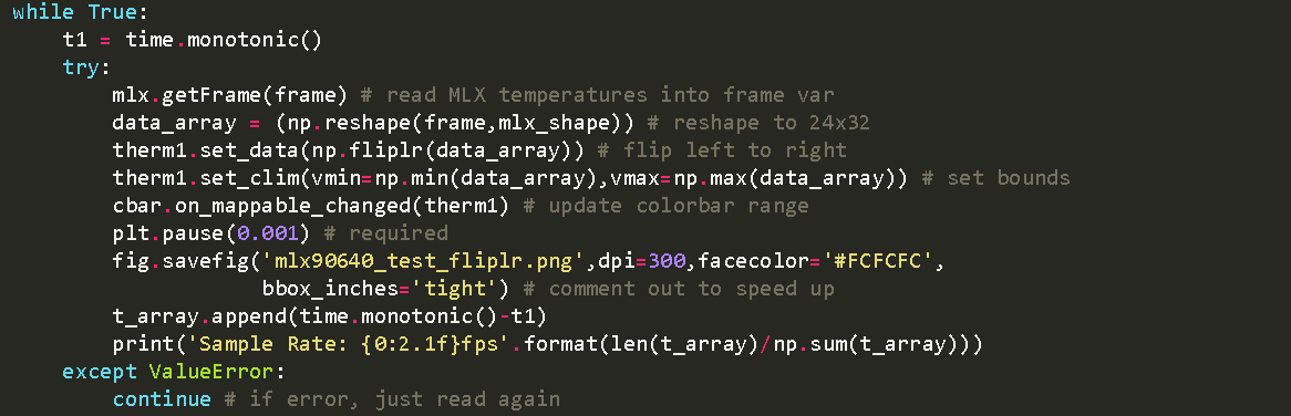
Code for Visualization
Step 4: Interpolating the MLX90640
The visualization code above is only a fast and straightforward way to get a display from your MLX90640 thermal array. You’ll have to improve your thermal camera’s resolution and the normal plotting speed for the last step.
First, you’ll need the ‘ndimage’ toolbox from the Python library to activate the zoom function. With this command, you can interpolate your camera’s 24×32 output to 240×320. Then, add the command to the visualization code above:

Next, you’ll need to enable the “blitting” method in “matplotlib” to get an updated frame rate for the interpolated image. Here’s the code you need for this:
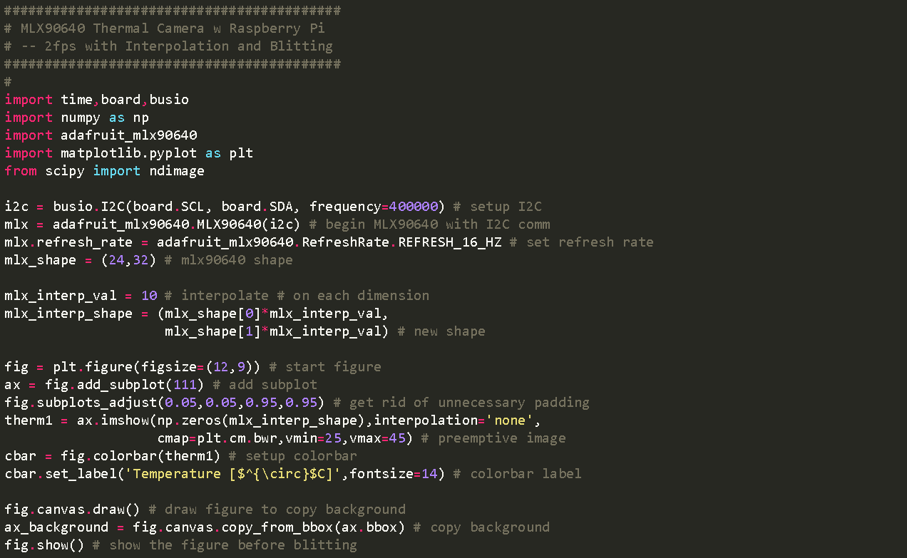

Blitting Code
Rounding Up
A DIY thermal imaging camera, which is less expensive, is a great way to capture infrared images without emptying your pockets. After creating one, you can quickly investigate any temperature difference with your thermal imager.
You can also build a thermal sensor that displays temperatures in high-resolution images. Though the resolution of a DIY thermal camera cannot compare to a commercial variant, it’s more than enough for detecting heat leaks or temperature changes in your area or an object.
Do you have any questions? Be sure to contact us, and we’ll be happy to respond and help you further.


