Contents
- 1 What’s the Idea Behind the Walkie Talkie?
- 2 How To Make a Walkie Talkie
- 3 How Do You Use the Walkie-Talkie Circuit?
- 3.1 Step 1: Connect the Mic With the Resistor and Capacitor
- 3.2 Step 2: Connect the Resistors
- 3.3 Step 3: Bypass Capacitor
- 3.4 Step 4: Connect 47 Ohms Capacitor to the Emitter Terminal
- 3.5 Step 5: Connect Another Bypass Capacitor to Emitter Terminal and Collector
- 3.6 Step 6: Join the Inductor and Variable Capacitor together
- 3.7 Step 7: Connect the Antenna to the Circuit
- 4 How Do You Use the Walkie-Talkie Circuit?
- 5 Bottom Line
What’s the Idea Behind the Walkie Talkie?
Before we dive into the steps of building a walkie-talkie, you need to be clear about how it works.
First off, it’s crucial to know that the walkie-talkie is incomplete without an FM transmitter and radio.
The FM radio acts as the receiver, while the FM transmitter helps to send the voice.

An example of a receiver
In other words, if you want to talk to someone with this device, you need a set of FM radio and FM transmitters.
And the same thing applies to the receiver. The goal here is to opt for any frequency between 88 to 108 MHz.
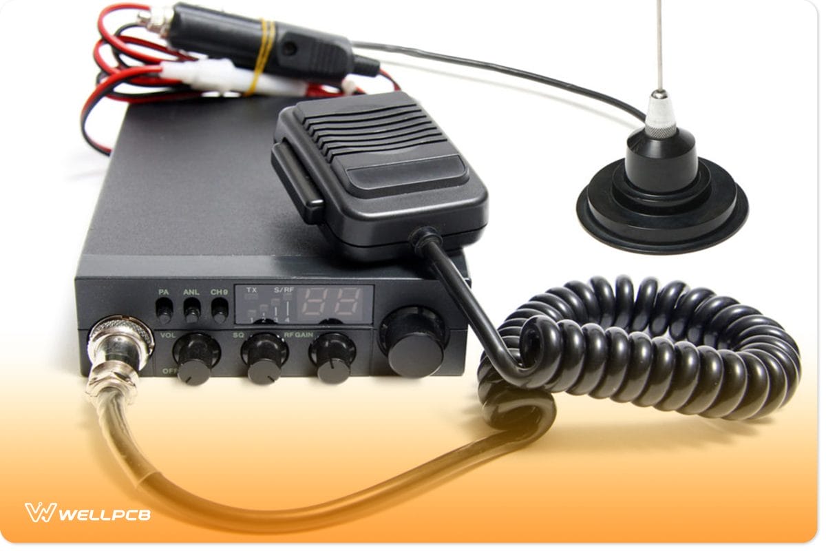
Two-way Radio transmitter and receiver
While you’re at it, ensure that your preferred frequency isn’t an operating FM station because it will disrupt your conversation.
That said, your communication on this device can either be full or half-duplex. Plus, there’s usually a switch in the circuit that allows you to change between the different modes.
So, the half-duplex refers to a bi-directional communication that occurs between two people. However, only one can receive it while the other can transmit it at once.
On the other hand, a full-duplex is when both parties can receive and send simultaneously.

A graphical representation of half and full-duplex communication
How To Make a Walkie Talkie
You’ll need a walkie talkie circuit design before you can proceed to make one.
First, we’ll talk about the two major sections: transmitter and receiver.
Also, we’ll break each of the sections into five different parts to help you understand the process better: Mixer, audio input, RF input, audio output, and RF output.
Components You Need
- RF antenna (1)
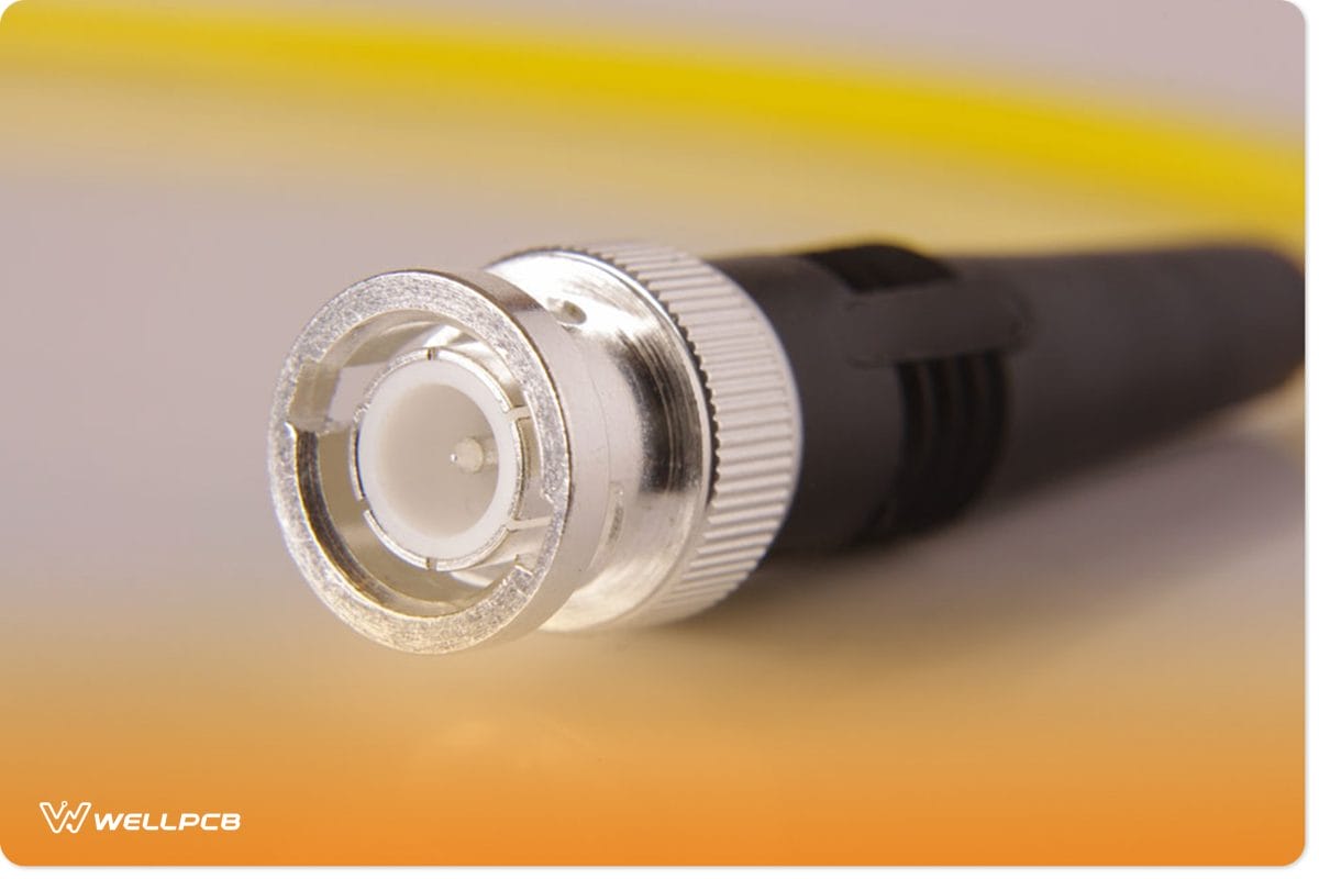
RF Antenna
- 12 Ohm speaker (1)
- 9v/500mAh battery (1)
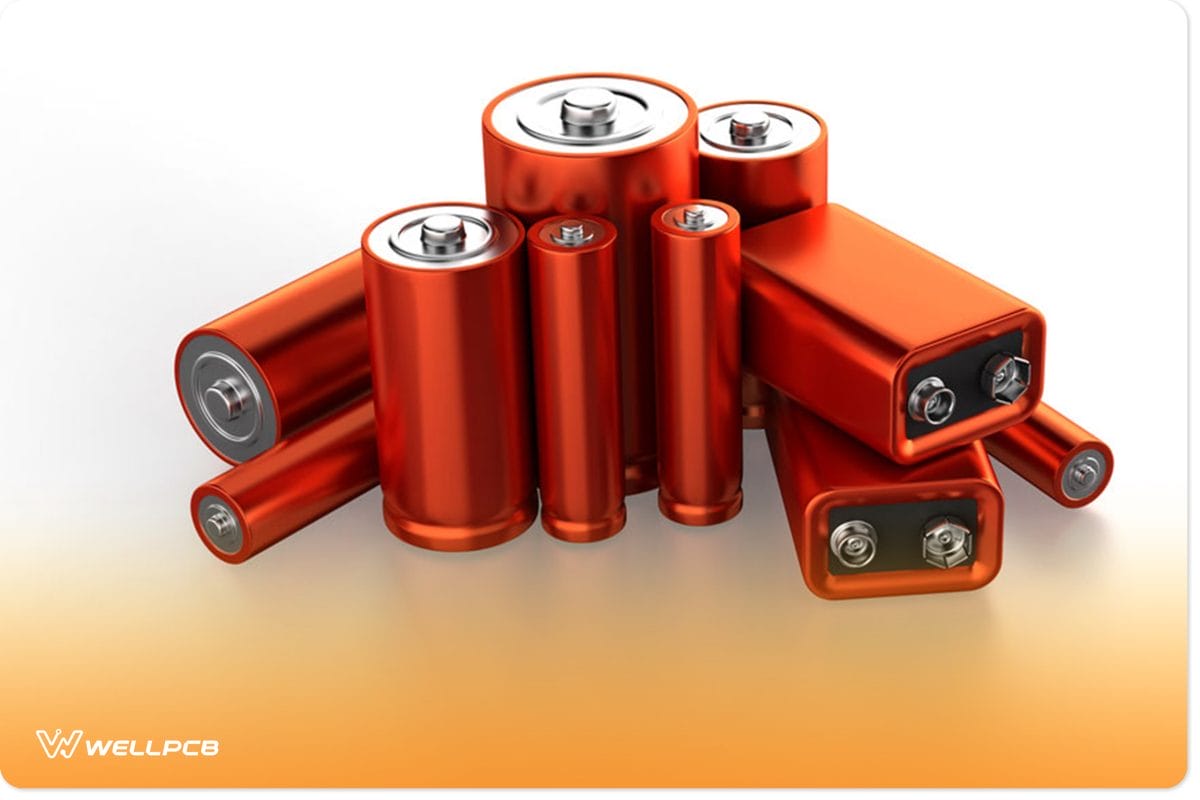
A set of 9v batteries
- Mixer IC SA612AN (1)
- Crystal Oscillator 8MHz ABM3B (1)
- Electret microphone (1)

Electret microphone
- 50k Ohm resistor (2)

A collection of 50k Ohm resistors
- 0.1uF capacitor (2)
- 1k Ohm resistor (2)
- Op Amp LM386 (2)
- 75k Ohm resistor (2)
- Op Amp NE5534 (2)
- 2.2uF capacitor (4)
- 10pF capacitor (4)
- 1uF capacitor (4)
- 100k Ohm resistor (8)
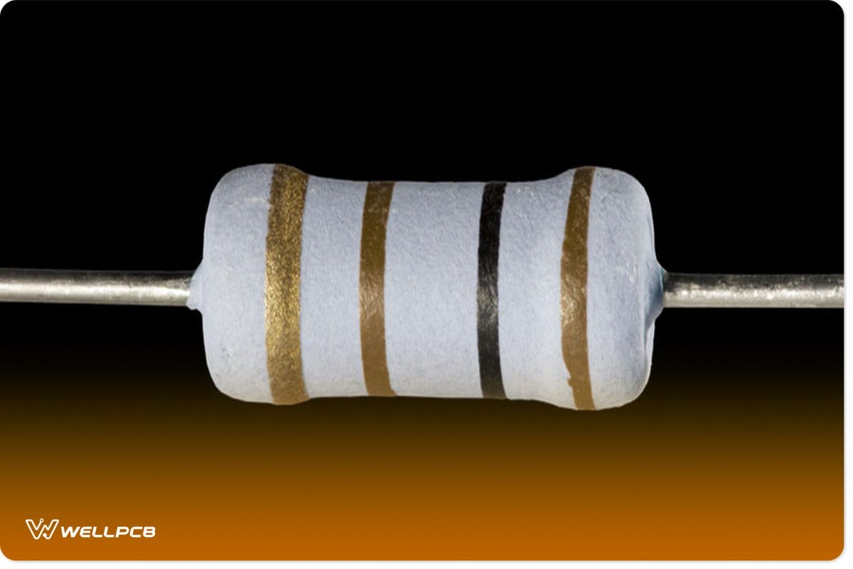
100k Ohm resistor
The Transmitter
In the transmitter section, here are the parts you’ll need:
Audio Input
The audio input happens to be the first section of the walkie-talkie. This portion of the circuit tends to take feedback from the user.
That is, the microphone helps to convert the sound from the user to electrical signals.
But, the signal from the microphone may be too weak. Hence, you can use an audio amplifier to boost the audio signals.
When that happens, the amplified output will move through the coupling capacitor C5. As a result, the DC elements will leave the amplified signal.
That is, only AC components will remain in the signal.
Afterward, the signal will move to a push button.
Mixer
The idea behind using a mixer is to modulate the amplified audio.
That way, the signal can travel through the air at a higher frequency.
In other words, wireless transmission is impossible without modulation.
So, the amplified signal will travel to the Mixer IC SA612AN. And it’s vital to connect the mixer to the 8MHz crystal oscillator. Why?
The crystal oscillator allows the mixer to control the amplified audio signal for the 8MHz carrier signal.
RF Output
At this point, the modulated signal moves to the RF output section. However, the signal goes to the RF amplifier before it radiates via the antenna.
So, you can use the Op Amp NE5537—since it has a higher bandwidth frequency response that makes it ideal for amplifying transmitted signals as RF signals.
The Receiver
If you plan to receive a signal from your walkie-talkie, it’s crucial to use the Antenna ANT1. With this, you can easily transmit voice signals.
That is, the audio signal that the antenna receives moves to the circuit’s RF input section.
RF Input
The moment your transmitted signal moves via the NNE5534-based amplifier, you can expect a signal boost. That said, any signal you subject to transmission tends to lose its strength. So, it’s vital to amplify the signal on the receiver’s end—which is the function of the NE5534.
When this happens, the boosted signal will move to the same mixer. But this time, the signal gets demodulated.
Mixer
The demodulation aims to return the signal to the original audio frequency. When this happens, the user can hear and comprehend the message.
That said, demodulation occurs when the input signal mixes with the crystal oscillator 8MHz. So, you have a split signal when two signals with similar frequency mix.
And you have a modulation when high frequency mixes with a low-frequency signal.
RF Output
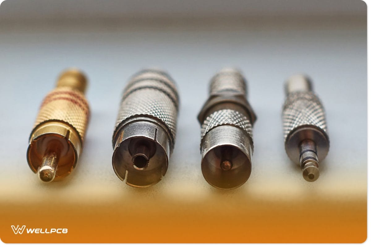
A collection of RF output collections
At this point, the signal from the mixer moves further to the output stage amplifier. You can get this amplifier by building with the LM386.
Next, the audio signal gets amplified and moved to the speaker connected itothe LM386 output.
With this, you can easily listen to the message transmitted from the other end of the walkie-talkie.
The Button
The DPDT button is essential when you’re building a walkie-talkie.
And it’s because the button’s position determines whether the circuit will function as a receiver or transmitter.
In other words, the button works by connecting with the output from the RF input section.
How Do You Use the Walkie-Talkie Circuit?
So, here are the necessary steps to take to build a walkie-talkie circuit;
Step 1: Connect the Mic With the Resistor and Capacitor
The first thing to do is to solder a 10K resistor and 10uF capacitor to the microphone.
The resistor offers DC voltage, and you transmit audio signals out of the walkie-talkie with the capacitor.
Also, the 10K capacitor only transmits the voice signals and blocks DC signals that attempt to enter the transistor.
So, you have to connect a 4.7K transistor to the 10uF capacitor to stop the current from entering the terminal base.
Step 2: Connect the Resistors
Next, join the 4.7K and 15K resistors across the terminal base.
By doing so, you’d create a voltage-dividing feature that provides DC for the transistors to remain active.
In essence, the transistors begin to act as amplifiers.
Step 3: Bypass Capacitor
This step involves you connecting a 4.7K resistor to a 0.1uF capacitor, which means you’ll bypass the capacitor. In other words, you’ll be passing high-frequency noise that comes from the microphone and reducing external transmitted noise that can disrupt communication.
Step 4: Connect 47 Ohms Capacitor to the Emitter Terminal
By carrying out this step, you’d reduce excess signals transmitted to the emitter terminal from the collector. Plus, you’d be providing more stability factors for the transistor.
Step 5: Connect Another Bypass Capacitor to Emitter Terminal and Collector
You’d have to connect another bypass capacitor to the emitter terminal and collector. It’s crucial to do this if you want to push out unwanted high-frequency signals to the ground. Plus, it also helps you create a clean transmission for your walkie-talkie.
Step 6: Join the Inductor and Variable Capacitor together
Merging both the variable capacitor and inductor brings about a tank circuit that oscillates between 88 – 108MHz. Then, turn the trim capacitor till you’re able to fine-tune the circuit to a stable and fixed frequency between 88 -108MHz.
Step 7: Connect the Antenna to the Circuit
First, you should know that you don’t need an antenna if you’re dealing with a 50 – 1100-meter range. As long as there’s no obstacle to the receiver between the above distances, the walkie-talkie can work perfectly.
However, if you plan to use the antenna for longer distances, it’s ideal to opt for a 1-foot insulated wire for your antenna. But, to find the best range, you can use a 3-feet antenna.
How Do You Use the Walkie-Talkie Circuit?
First off, you have to build two circuits. These circuits will allow two people to use them. Since the circuit is in the receiver state by default, the first user must press the button to enable its transmitter state. At this point, the user can speak.
Once the first user finishes the message, the person has to say “Over”—to indicate the end of the message transmission. Afterward, the person can release the button—so the circuit returns to the receiver state. When this happens, the second user should have gotten the first user’s message.
When that happens, the second user can press the button to activate the circuit’s transmitter mode and reply to the first user’s message. And the users can continue the cycle.
Bottom Line
A DIY walkie-talkie is a super cool project to work on, considering that anyone can use the device. Plus, the portable radio helps you have fun with friends or communicate between rooms.
Children aren’t left out, either, as they can boost their game of “hide and seek” with this tool. Interestingly, the walkie-talkie isn’t a complicated device to construct.
All you need to do is have a circuit diagram or follow the one in this article. Then, get your materials in place and build.
What do you think about this guide? Are you having issues with any steps?
Please feel free to contact us.