Contents
What is a Dpdt Relay?
A dpdt relay, also known as a Double(D) Pole(P) Double(D) Throw(T) relay, is an electromagnetic device used in electric motors. A dpdt has two inputs. Additionally, each piece of information has two outputs.
How Does a Dpdt Relay Work?
A relay-insulated coil automatically flips changeover switches whenever manual switching is impossible. Therefore, it works as a control circuit. Often, relays use devices that look like transistors to carry the electrical loads when applying power. However, we have some types called electromechanical relays. These relays are easy to comprehend.
The relays have a low-voltage application to turn the electromagnet into a magnetic field. Moreover, it also has a contact switch to control the magnetic circuit. When the maintained course is within the magnetic field, the relay mainly acts as if someone flips the button with the contacts in position.
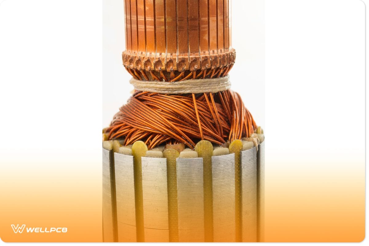
(a section of an electric motor.)
Owing to the operating principles of a household switch, it will always remain how you leave it. If you switch it on, it will remain so unless you switch it off and vice versa. However, a relay coil behaves differently because its basic operations require electromagnetic operations. When the magnet present is in a field at deactivation, the electrical switches are relaxed. It explains that the external circuit will turn on whenever the current ratings are off; otherwise, it causes device failure.
A dpdt relay is a type of relay that has a double pole. Consequently, this double pole can switch the circuit on both sides. In addition, the dpdt also has a double throw. This double-throw means that the course can easily switch between wires rather than just control output by turning it on or off using electric power systems.

(an example of a household switch.)
How to Connect Dpdt Relays in the Circuit
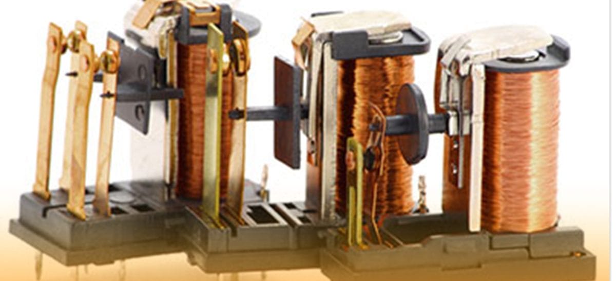
A dpdt is an electromagnetic relay containing a solenoid with a wrapped insulated coil of wire around it. This device has several contacts and a relatively movable iron armature motion. Also, it has a magnetic flux of a low reluctance path given off by an iron yoke. Not to forget the normal circuit conditions it possesses.
(inductive coil icon.)
Change the direction of a motor with a dpdt relay.
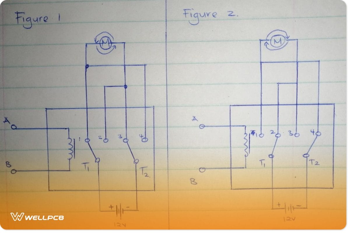
(Circuits that explain the operation of a dpdt relay in a motor.)
We are using a 12v battery and sets of contacts depending on the printed circuit board from the circuit design. Similarly, we can use any continuous power battery in the relay coil connection. Importantly, we connect the contacts in parallel. The positive end of the power source will connect to the T1 terminal, while the opposing end will connect to the T2 terminal. Also, we have DPDT contacts 1 and 4 connecting and DPDT auxiliary contact sets 2 and 3.
When there is no trigger voltage passing through the single coil, the positive end of the battery will connect to T1. Then, this will relate to contact 1. Additionally, the opposing end will attach to T2 and contact 2. These contacts connecting to T1 are otherwise known as positive-guided contacts. It makes that motor turn in a clockwise direction.
When the vice versa, and we apply trigger voltage to the single-coil, the automotive relay automatically switches. Consequently, this causes a changeover of contacts in the circuit track, creating contact resistance. Next, T1 from the battery’s +Ve connects to contact 2, whereas T2 from the negative terminal connects to get 4. As a result, this alternates the motor’s direction of rotation to the anticlockwise order.
(battery icon showing the positive and negative ends.)
Switch between 2 different loads using dpdt switches.
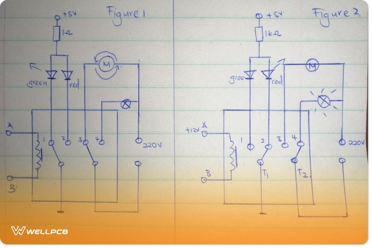
(circuits that explain the switch between two different loads)
The coil terminals connect to a fan from the contactor coil in the first circuit and green and red LED bulbs. The bulbs are the lighting loads. When no direct current is applied to the coil form, the green LED and the fan turn on. However, when there is a current application to the coil, as in circuit 2, the coil current switches the relays. Therefore, this turns on the red LED and the light bulb.
Uses of a Dpdt Relay
Used in an industrial motor starter to pull apart two electronic circuits. Then, it connects them magnetically in the presence of a magnetic field.
We also use them in electronic devices when the electronic switch is relaxed. This links electronic circuits that operate on a low contact current to those on a higher contact current.
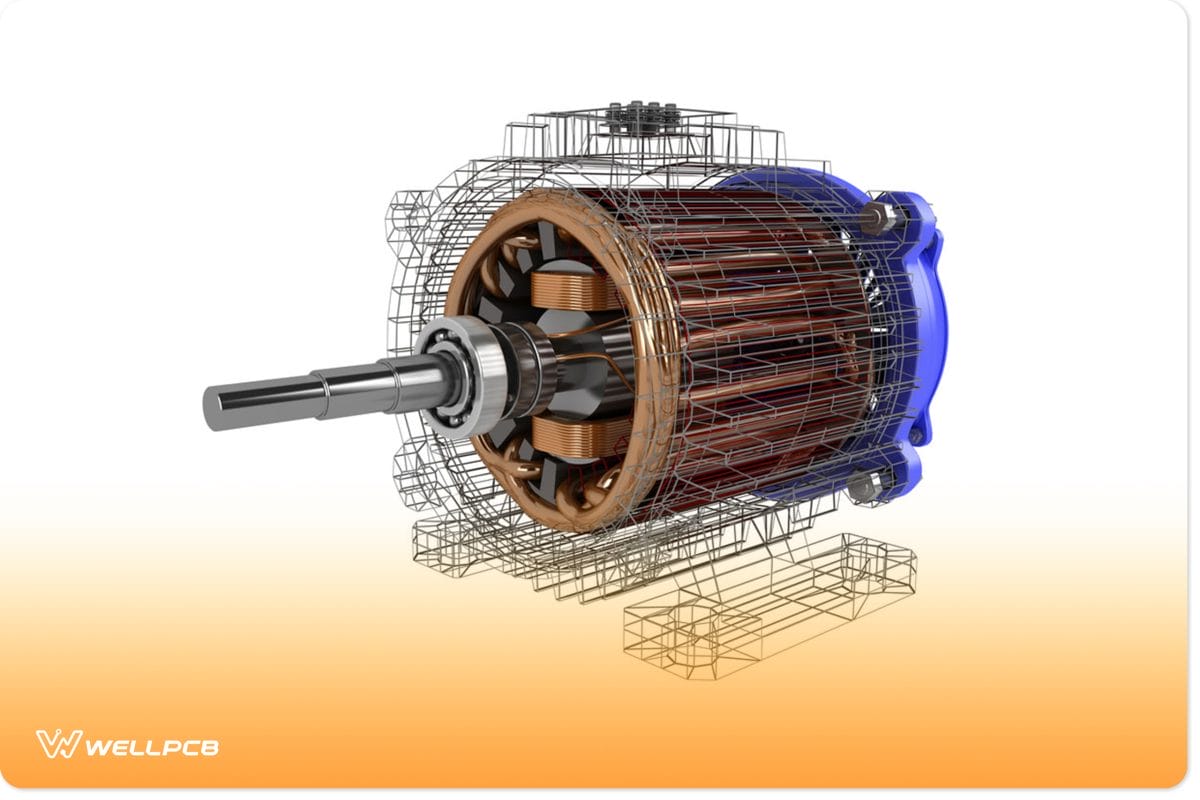
(an electric motor.)
Summary
A dpdt relay is very common in many electronic devices. It controls the circuit, making sure there is no waste of current.
We hope this article has brought some light to the dpdt relay. If you liked it, please check out more of our articles. For further queries, please reach out to us!