Power failures present a significant hindrance to our everyday lives. As a result, we immediately lose normal lighting operations during such an outage, putting us in sudden darkness. Thankfully, an Emergency light circuit provides the perfect solution to that problem. These turn on immediately once the regular source no longer distributes electricity to a lighting fixture.
This guide aims to put you on the right track toward building a simple emergency lamp circuit. With such an installment, you will no longer need to worry about staying in total darkness.
Contents
What is an Emergency Light & How it Works?
(Power outages can occur unexpectedly in a building.)
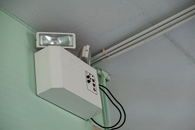
An emergency light serves as a backup lighting option whenever a power failure occurs in a building. It consists of a power circuit that automatically activates the battery-powered light during an outage. Furthermore, emergency lights provide people with instant illumination when they find themselves in the sudden darkness, making emergency fixtures very convenient.
With emergency systems installed, an individual can locate another lighting source, including a generator or an inverter, until power restores.
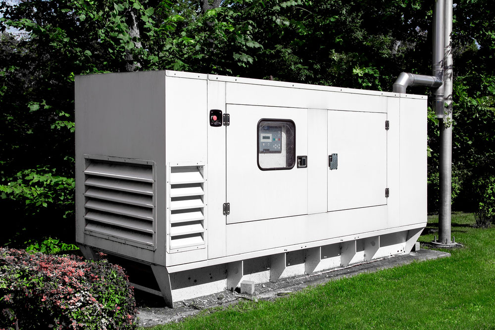
(A generator also provides backup power during an outage.)
Each emergency light connects to a building’s electrical supply. Generally, when the power source cuts off, AC power also stops flowing. In effect, this triggers the battery backup power to switch on, which delivers DC power to the lighting fixture. Those batteries need a full recharge within 24 hours after AC power restoration. This will allow it to last for at least 90 minutes during power failure. Even then, a battery pack can provide power for 120 minutes. Some emergency lighting circuits meet the minimum illumination levels for mandated building codes.
Additionally, we recommend testing emergency light systems every month for one minute to ensure high performance. You should also discharge the battery for half an hour once a year. Batteries need a cyclic operation to function normally during a blackout. A 30-minute discharge will ensure that it will operate without any issue when needed.
How to Make an Automatic LED Emergency Light Circuit
Due to its light output, this circuit utilizes LED lights, making it more power-efficient and brighter than an incandescent lamp.
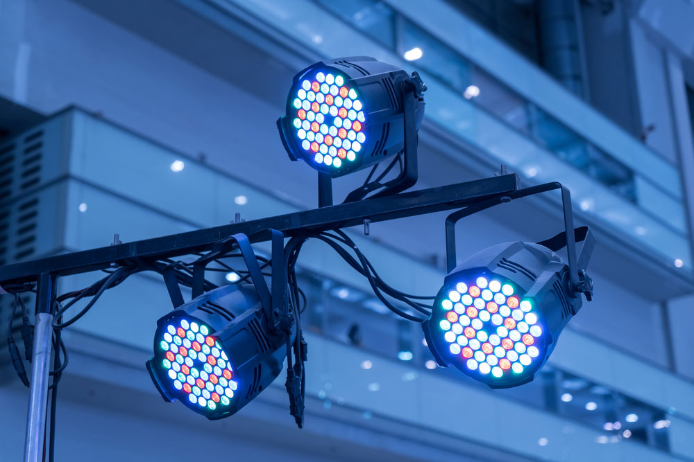
(LED lights consume less power in comparison to an incandescent lamp.)
less power in comparison to an incandescent lamp.)
You will need the following parts to build a simple emergency light circuit:
- 909 500mA step down transformer – 1x
- Two-way switch with double poles – 1x
- 12V SPDT single pole double throw relay – 1x
- 6V/12W LED light panel – 1x
- 7806 IC regulator – 1x
- IN4007 diodes – 4x
- 1K resistor – 1x
- 1000uF/35V capacitors – 2x
- 470uF/16V capacitor – 1x
- Red LED indicator – 1x
- 6V/5A rechargeable battery
- Printed circuit board
- Soldering iron
diy emergency light steps:
Step One: Build the rectifier circuit
First, create the full-wave rectifier circuit by wiring two diodes to the 12V relay’s coil and wayside terminal. Next, connect the final two diodes to the input channel of the IC regulator. Lastly, wire the transformer’s output sides to each bridge rectifier.
Step Two: Connect the switch
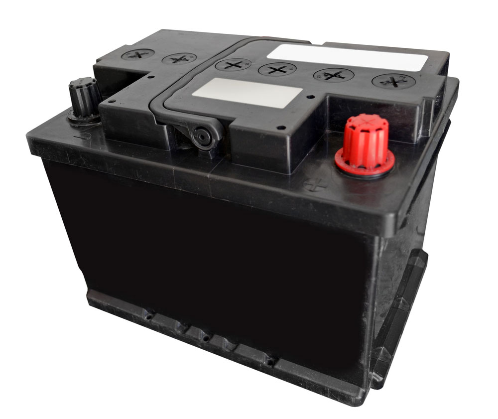
(A 6V industrial rechargeable battery connected to a circuit.)
Join the 6V battery’s positive end to the relay’s pole. Afterward, you will need to connect the relay’s 5th terminal with the switch’s 1st terminal. Then, form a connection from the IC regulator’s output terminal to the 3rd terminal of the switch. Lastly, link the switch’s pole to the 6V LED light’s positive side.
Step three: Connect the ground lines.

(Ground lines on a circuit board.)
The next step involves connecting the ground lines. Connect the battery’s negative terminal and the coil’s 3rd terminal to the ground. Next, connect the IC regulator’s base pin along with the LED’s negative pole to the circuit board’s ground.
Step four: Integrate the capacitors.
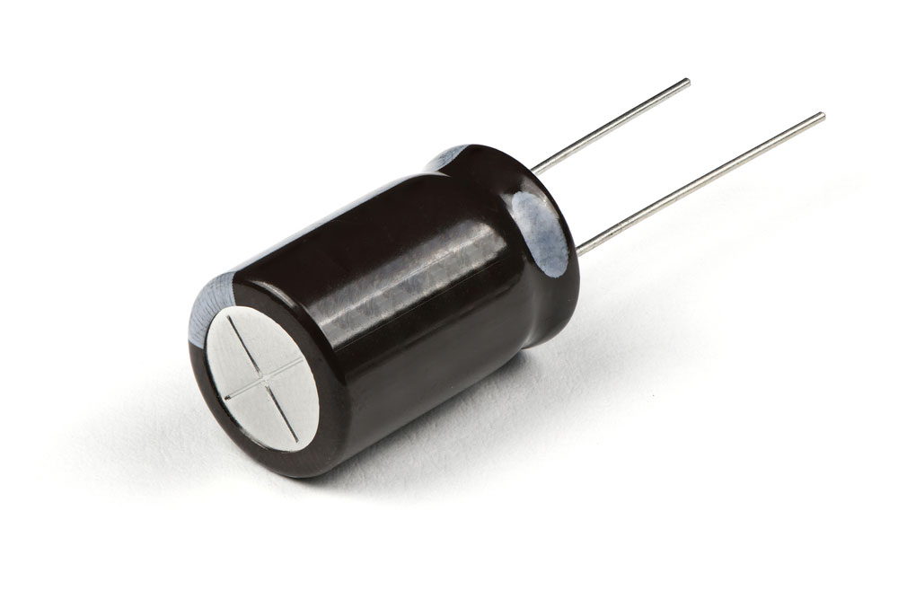
(Image showing a capacitor.)
Finally, implement two 1000uF capacitors opposite of both rectifiers (all four IN4007 diodes) and the ground line. Next, integrate both the red LED and 1K resistor in a series opposite of the 1000uF capacitor. Finally, add the 470uF capacitor crosswise to the IC regulator’s output.
Circuit working principle:
First, the AC mode bridge rectifier, which supplies the battery with AC voltage (100mA), delivers power to the transformer’s coil. This occurs after the AC supply activates. Because of this effect, the relay’s pole forms a connection with the battery and DC voltage.
Then, the other bridge distributes voltage to the IC regulator, which causes a voltage drop from 9V to 6V. That way, the LED lights will illuminate after the switch delivers power to its pole and 4th terminal. Therefore, the battery provides power to the LED panel.
This circuit also serves as a battery charger when you don’t need the light. Reversing the switch provides this functionality. In such a setup, the switch forms a connection between its 1st terminal and pole. Then, the LED connects to the IC regulator’s positive end. Therefore, the LED stays deactivated while the battery charges.
The circuit can also serve as an automatic emergency light. While the main supply switches off, the relay’s pole transmits current to the relay’s 5th terminal. That puts it in the not open position. In the current configuration, the battery sends electricity to the LED lights, causing them to illuminate. However, if you don’t need to charge the battery, then disconnect the AC supply and connect the switch’s 2nd and 3rd terminals.

Emergency Light Application
The emergency lights have applications during a power outage and in poorly-lit areas, including dark and storerooms.
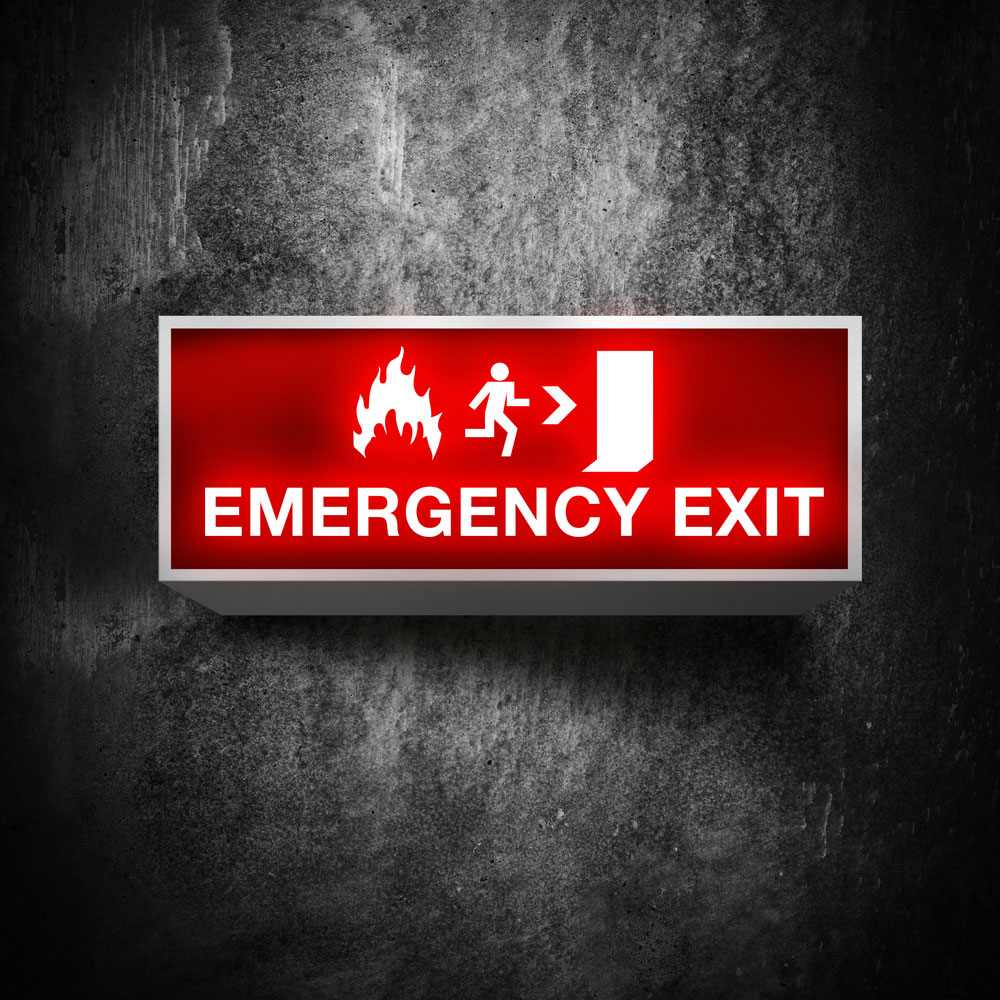
(Emergency light applications include an exit sign.)
You can also install these in a building, home, study room, and workplace. They prevent power failure from disrupting everyday tasks.
It can also serve as an emergency lamp for exit signs.
Summary
Overall, emergency lighting systems provide a great backup lighting option when the normal power source becomes disrupted. These usually rely on battery power to illuminate a lamp, which switches on automatically. In effect, this will illuminate any dark areas. We also noted that a licensed professional must ensure the batteries can function normally. We also advise you to fully charge the battery 24 hours after power restoration from a blackout. After all, this technique will enable the emergency lights to illuminate for 90 minutes during the next blackout.
Do you have any questions regarding automatic emergency lights? Feel free to contact us!


