Have you ever thought about why it’s possible to control the speed of vehicles? Most vehicles are capable of running at dangerous speeds and can cause fatal accidents if not controlled. The trick here is an ESC (Electronic Speed Control) circuit that offers all the speed control you’ll need for any vehicle project. But, you may wonder: How can I use an ESC circuit for my next project?
In this article, you’ll learn how ESC circuits work and how to make one. We’ll also let you know the secrets to choose the perfect ESC.
Are you ready? Let’s begin!
Contents
What is an ESC Circuit?
ESCs are electronic circuits with speed control capabilities that also change motor speed and route. Also, they can work as a dynamic brake.
Motor
Interestingly, ESC circuits are famous in radio-controlled devices with an electric power source. It also controls brushless motors that produce electric power.
Also, you can add an ESC circuit to a device in two ways.
The first method includes setting an ESC as a separate unit that you can add to a throttle-receiver control channel. Secondly, you can add ESC to the central receiver component. We see many instances of the second method in toy-grade R/C cars. Some R/C cars use exclusive hobbyist electronics to combine the ESC and receiver on a single board.
How Does ESC work?
ESC technology is pretty important in the automobile industry. It prevents cars from reaching dangerous speeds, skidding, or losing control while driving. It can activate breaks automatically and ensure the vehicle steers correctly.

Car Driving Fast
But how does it work? As we mentioned earlier, ESC can control brushless motor speed. It does this by adequately using MOSFETs, creating a magnetic field to rotate the motor.
An ESC has six intervals, and how fast it goes through them determines the motor speed.
What Components Make up an ESC

Man Building a Circuit
Here are the components you can use to make an ESC circuit:
- Solder jumper (for changing the PWM input signal type and rotation direction CW/CCW)
- Solder pads (for the 3-BDLDC motor phases)
- Positive (+) and negative (-) LIPO connections
- State LED
- GND reference of PWM signal
- PWM signal input (servo signal)
Types of ESC Circuits
You can use two types of ESC for your projects. But it depends on your project’s specific requirements. They include brushed and brushless ESC.
Brushed ESC
Brushed ESCs have been around for a while and were the first produced electronic speed controllers. As the name implies, brushed ESC circuits can control a brushed motor’s voltage. Plus, a brushed motor can mechanically run itself as long as you apply voltage.
The brushed ESC can rapidly turn the above voltage on and off—depending on the motor’s speed. Also, brushed ESCs are cheap and work in many RC vehicles.
Brushless ESC
The brushless ESC is a more advanced version of the speed controller that uses a 3-phase AC power, like a variable frequency drive (VFD), to operate brushless motors.
Brushless motors are more popular because they have better power, longevity, lightweight, and efficiency features. However, its improved features make it more expensive.

Applications of ESC Circuits

Vehicles
The main applications of ESC circuits are in the automobile industry. So, you can find ESC circuits in vehicles and remote control applications. Some of these applications include:
- Electric aircrafts
- Boats
- ESC firmware
- Electric cars
- Quadcopters
- Helicopters
- Airplanes
- Electric bicycles
The Function of Electronic Speed Control
ESCs use speed reference signals to control the speed of field-effect transistor-switching networks. It does this by adjusting the duty cycle or switching the frequency of the transistors.
In the case of a brushless DC electric motor, it’s necessary to have different speed controls. Why? Because changing its armature voltage can control the motor speed. Plus, these motor types use general operating rules. Such rules include “You can change motor speed by changing the timing pulses for transmitting current to different motor windings.”
Also, remember that the brushless DC electric motor is more complex when compared to its brushed counterparts.
The phase of the ESC changes according to the rotation of the brushless motor. Plus, you can use “back EMF” to detect the motor’s rotation. If that’s not working for you, other variations come equipped with hall effect sensors or optical detectors.
Ultimately, there are speed controllers that depend on programming. These ESCs include user-specified options, including permissions to control brake, acceleration, and revolution timing and directing. You can also reverse a motor’s direction by switching any of the ESC’s three leads towards the engine.
Features of an Electronic Speed Control
An electronic speed control’s main features include a low voltage cutoff, brake, and a battery eliminator circuit. Let’s look at these features through ESC in airplanes.
ESC in airplanes has three wire sets that control different plane parts. The first wire-set plugs into the plane’s battery, while the second utilizes a servo wire to plug into the channel of the receiver throttle. Lastly, the third wire set is responsible for making the motor work.
Electronic Speed Controller Circuit
In truth, most electronic speed controllers utilize microcontrollers that understand the input signal and control the electric motor through a firmware program.
Plus, it’s possible to change the settings of the firmware program and use it for alternate reasons, like using your ESC for a different application.
Also, some manufacturers prefer building inbuilt ESCs with upgradeable firmware, while others prefer solderable types. Manufacturers sell the solderable ESCs like they sell black boxes—through proprietary firmware.
Now, let’s look at how to build an ESC circuit.
How to Build an ESC Circuit
Before you start, here are some components you’ll need for this project:
- Arduino Nano (1)
- 10KΩ potentiometer (2)
- 1uf Capacitor (2)
- L6234 IC (1)
- 1N4148 Diode (2)
- 1Ω resistor (5)
- 470nF capacitor (4)
- 100nF capacitor (1)
- 10nF capacitor (1)
- 220nF capacitor (1)
- 1kΩ resistor (4)
- 10kΩ resistor (3)
- LM393 Comparator (2)
Step one: Build the Circuit
Follow the schematics below to assemble this circuit.
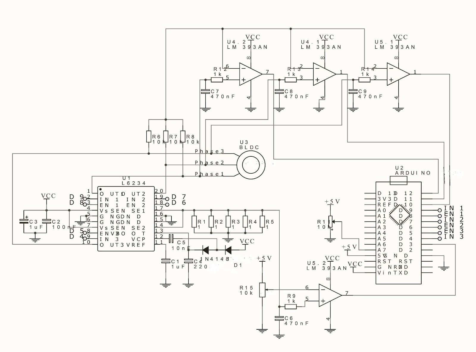
Schematics of ESC circuits
Step 2: Upload your Code
Indeed, there are four different codes you can upload. Each code has a different control style; try them all out to choose your preferred code.
Sets the circuit to use the analogRead function for current measuring (Code 1).
Programs the circuit to use pin 3’s external interrupt for current measuring(Code 2).
Programs timer 2 to control current chopping(Code 3).
Sets the circuit to use pins 10, 11, and 12’s interrupts for step switching(Code 4).
Choosing the Right ESC
Before choosing an ESC, you must ensure it matches your motor type. Hence, brushless ESCs should be for brushless motors only.
An electronic speed controller is essential for projects requiring speed control. The most common applications to enjoy ESC circuits are in vehicles and R/C cars.
More importantly, you must always choose the exact ESC for your motors, or your circuit won’t be functional.
What do you think about ESC circuits? Feel free to reach us if you have any questions.


