Do you know that the ESP8266 can permit you access to your wireless network? What about the ESP32? Available at a low price and also, it is environmentally friendly? If you are not too familiar with all of these, then you might need to take a step forward.
However, rest assured, we have made available to you the ups and downs of the information concerned with the ESP8266 without leaving the ESP32 behind, and we believe this would be of great help in choosing which best suits you your status and condition.
After the tutorial section, we would direct you to the exact place to make your purchase, cool right! So you can do well to take a seat, calm your nerves and take your time through what we have for you.
Contents
The ESP8266
1.1 Definition:
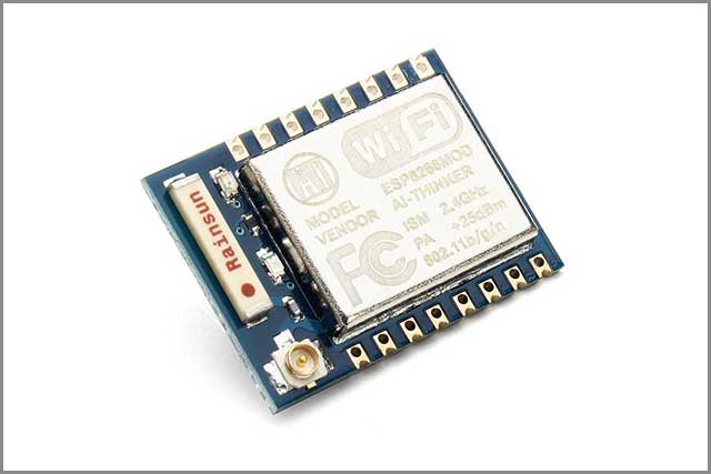
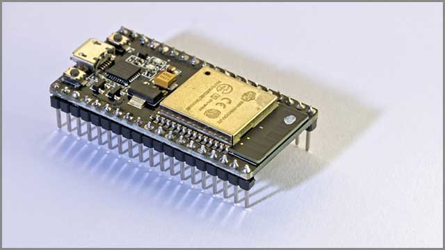
The ESP8266 is a user-friendly, pocket-friendly, wireless fidelity microchip that includes a full transmission control protocol (TCP) or internet protocol (IP) stack, thereby enabling access of any microcontroller to your wireless network (WIFI). In a simple form, the ESP8266 is a WIFI microchip having micro-controlled and TCP capability.
For history’s sake, this chip initially became noticed by western producers in 2014. This chip enables a microcontroller to a wireless network and offers another advantage such as low cost.
The various applications of the ESP8266 include; Home automation, portable electronics, access point portals, IoT projects, bulbs, sockets, and so on. In more than a month, the ESP8266 project widened by adding an open-hardware platform. It was done when the developer committed the devkit V0.9. It is the file for the ESP8266 board. NodeMCU advanced to supporting the MQTT IOT protocol when the MQTT was moved from Contiki to the ESP8266 SOC platform by Tuan PM.
1.1.1 The ESP8266 usage
Concerning the ESP module, there are different processes and IDEs obtainable for use with this, and out of these methods or techniques, the most regularly used is the Arduino IDE. It is strictly advisable that the ESP8266 be used with 3.3V; this is because any other like 3.7V can be terrible for the module. So, it is necessary to find a competent board that supports 3.3V, which is why we will be using the FTDI board.
However, as an alternative, the Arduino board can be used if you cannot get the FTDI board. At least, if you are expecting any challenge with the ESP8266, then you should be looking at the aspect of the power-up. Moreover, to rectify this, you would need to design a small voltage regulator for 3.3V with the ability to offer the least 500mA.
1.2 ESP8266 Programming
There are several methods or ways adopted when it comes to programming the ESP8266. The Arduino IDE is ubiquitous in programming the ESP8266. Why? It’s simple! Even for starters, it can seem relatively more comfortable, and for those who have been in it for quite some time now, it would only seem like a piece of cake. Well, there are situations whereby you might need to do a little trick to advance more on the Arduino.
In this kind of situation, you might want to look into an official SDK to program it in the honest C. in programming, there are different components required, and they include; ESP8266 Board, an available WIFI network, USB cable, a system or computer that can run the Arduino IDE, and so on.
NodeMCU ESP8266
The nodeMCU comprises firmware that operates on the ESP8266 wireless fidelity (WIFI) SOC. The nodeMCU points to the firmware, which uses the Lua scripting language and not the development kits. Following the ESP8266, the nodeMCU was designed in December 2013 and is commonly used in IoT applications. A brief history review showed that Hong assigned the primary file of nodeMCU firmware to GitHub on the 13th of October, 2014. Unfortunately, the primary designers left the firmware project, but some other independent contributors carried on the project. As of 2016, nodeMCU already contains more than 40 modules.
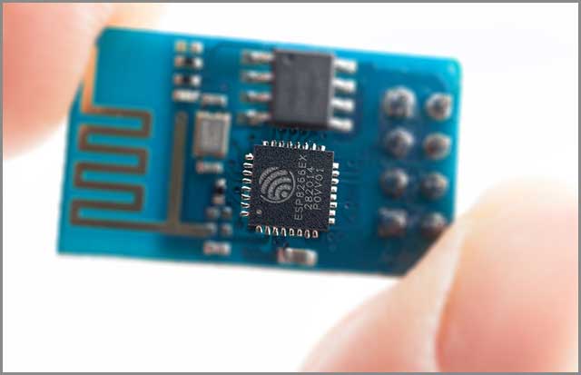
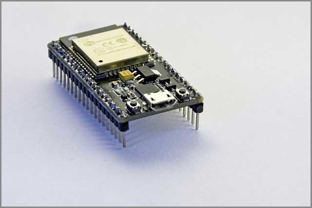
ESP8266 Pinout
In the ESP8266 pinout, there is one crucial thing to note: not all pins are suitable, or there are pins meant for some particular things. Most people often take the nodeMCU as the ESP-12E, but this doesn’t seem right. Unlike the ESP-12E that uses the UART for recording, the USB is responsible for this in nodeMCU. When you program, use numbers in front of the GPIO (AO, DO, D1, D2, D3, D4, D5, D6, D7, D8). Due to the difference in the nodeMCU pins, some pins are up while others are down; put the oscilloscope at the edge of the nails. The tests on the input and output showed that analogRead seems compatible only with ADC, digital white is not compatible with ADC and GPIO 6,7,8, and 11.
We have Power pins which include the GND (regular for all logic and power), USB ( if connected, it is a positive voltage to the USB jack), 3V (the 3V is output from the regulator with the ability to offer a 500mA). Also, we have the Logic pins. All logic pins are 3.3V, and it is the most common purpose pin suitable for the microcontroller. We also have the serial pins, that is, the RX and TX pins. They are both V and 3.3V, respectively, but a difference between them is that the RX is the input into the module, while the TX is output5 from the module.
ESP8266 Arduino
We should know that there are pretty many IDEs that can be used in the programming of the ESP8266 and the Arduino IDE are a perfect one. This whole thing was made easy when the ESP8266 community made available the avenue for the programming of the ESP8266 using the Arduino IDE. In using this, no external microcontroller is needed, enabling you to write sketches with the aid of public Arduino libraries, running them directly on the ESP8266. The ESP8266 Arduino core is readily designed to come along with libraries to connect over WIFI (wireless fidelity) with the aid of TCP and UDP. The ESP8266 has fortunately made this whole thing easier; how? Since the community moved a bit higher by designing the Arduino addon, it has become easier for starters interested in programming the ESP8266. It is always advisable to start with this because it is environmentally friendly.
Ivan Prokhorov, alongside the other community members, has made it more comfortable with their work resulting in the design. Adding a third-party board to the Arduino IDE is a much easier task with the new board manager.

ESP8266 Projects
The ESP8266 is a WIFI module that Espressif Systems designed. It is a microcontroller that performs the functions or activities related to WIFI. Due to this reason, it is commonly used broadly as a WIFI module along with other boards like the Arduino.
5.1 Creating a Web server
Now, you probably understand that the ESP8266 is not only expected but also inexpensive, user-friendly, and an excellent option in connecting your hardware to the internet. These days, we have many IoT products readily available in the market, and various projects have been made using the ESP8266. Among the projects is the necessary interfacing with other microcontrollers, tracking on Google maps, monitoring of air pollution, and so on. The idea behind doing this is majorly based on the connection between the ESP8266 and STM32F103C8.
In creating a web server, we will use the theESP8266 WIFI module and the STM32F103C8 board; other components needed are the hotspot and a laptop. To maintain communication with the ESP8266, AT commands are very useful.
The below information contains some of the AT commands used.
|
AT COMMANDS |
FUNCTION |
|
AT+GMR | This command shows the details of the firmware. |
|
AT+RST | This command is used in to RESTART module. |
|
AT |
This command depicts the Acknowledgement returns “OK.” |
|
AT+CIPCLOSE | This command is used to close the connection of TCP or UDP. |
|
AT+CIPSTATUS | This command gets the status of the connection. |
|
AT+CIFSR | This command gets the IP address. |
Please do not forget that these are not the only AT commands used; a few of them are only highlighted in this section.
The STM32F103C8 contains precisely three sets of UART serial communication. In connecting the ESP8266 pins with the STM32 pins, refer to the table below.
|
ESP8266 |
STM32 |
|
RX |
PA2 |
|
TX |
PA3 |
|
GND |
G |
|
VCC |
3.3V |
|
CH_PD |
3.3V |
5.2 Projects based on the Arduino ESP8266
There’s an endless list of project ideas based on the ESP8266 WiFi module to keep you experimenting, as you can quickly go through all of them. To give you a hand, you can leverage your tinkering with IoT platforms. One of them is Ubidots, an intuitive interface that allows you to display your project’s data and control your devices remotely.
– Web controlled a servo using Arduino and Wi-Fi
– IoT based Air pollution Monitoring
– Low-cost Smart Planter using an ESP8266
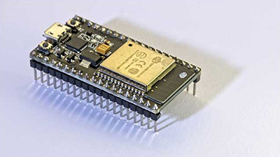
ESP32 VS ESP8266
More like the ESP8266, the ESP32 is an excellent cost choice and offers a low power system on a chip microcontroller. Choosing between going for the ESP32 or the ESP8266 can be pretty challenging, but it depends on the type of project you want to engage in. They both have their advantages and disadvantages. So at this stage, you should be so concerned about which one to choose to go along with what you want to do.
When considering the cost, the ESP8266 is relatively cheaper when compared to ESP32. The ESP266 might not be equipped with very high utility, but it is an excellent choice for individuals working on simple DIY IoT works. Regarding software, support ESP8266, and of course, it is user-friendly. A disadvantage related to the ESP8266 is that its pins might not be sufficient for your type of project, and in cases such as this, there is no other choice than to go for the ESP32.
The ESP32 comprises more GPIOs which have many functions, making it more powerful compared to the ESP8266. The ESP32 supports Bluetooth functions and has more fast WIFI. Many people often think that it is more complicated to work with the ESP32 than the ESP8266, yes! It might be true but not accurate. It can seem easy to use when using it with Arduino language. Since nothing ever comes with an advantage attached, one of its limitations is that it is more costly than the ESP8266; unlike the ESP8266 that works with most software, not all software has been designed perfectly to suit the ESP32.
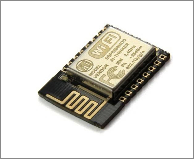
Module
The ESP8266 is a wireless fidelity (WIFI) module that is common for its IoT applications. It works with a voltage of 3V but can also go as far as 3.6V. In powering it up and serial connecting, a level of technical know-how is required. The module can permit any microcontroller the right to a WIFI network. Of course, every ESP8266 is designed with an AT command firmware, insinuating that it can be connected with the Arduino device, thereby permitting you unlimited wifi capability.
The fantastic offer this whole thing has to give is something that cannot just be overlooked without ever forgetting that it is a competitive and ever-developing community. Its GPIOs can permit its integration with sensors, enabling it to be a robust processing and storage-capable module.
Tutorial
In this section, we would highlight the necessary steps required in programming the ESP8266, and here, we would be programming using the Arduino IDE. With the intervention of the Arduino IDE, using the ESP modules seems relatively more straightforward. The Arduino community has made available its board manager, saving the stress of learning the instruction documentation of the ESP module.
We would make flash a LED light by using the Arduino IDE to program the ESP module.
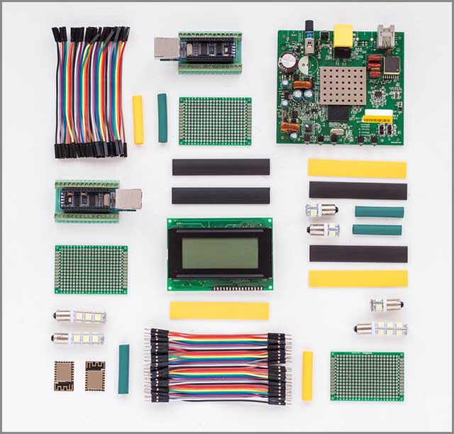
In order to program the ESP8266 using the Arduino IDE, the components required include:
- Arduino IDE
- ESP8266 module
- FTDI breakout board
Step 1: The first thing is to ensure the availability of the Arduino IDE. If you don’t have it, you can download it. Ensure that you download versions like1.6.5 and above; it is the most preferred.
Step 2: scroll to file, then preferences. Scroll down to almost the bottom of the page, and you will see a tab with the title “Additional board manager URLs” written at its front. Click on the space and type this link.
Step 3: in the third step, click on the tool, scroll to ‘board’ and click, then click “board managers.” Search for this sentence “esp8266 by the esp8266 community”. It will pop the search result, click on ‘install’ located on the resulting space. After completion, navigate to tools, click on boards, then click on Generic ESP8266 modules.
Step 4: you will see a screen where you can upload the blink program, locate the file by clicking on the file, then examples, followed by ESP2666, and click on the blink.
Step 5: This is the stage where the FTDI board is required. Now, connect the ESP8266 module and FTDI board. Set the jumper switch and pull down the GPIOO, then power up the modules. It can also be reset by pressing the push button.
Step 6: press and wait for the upload to complete. To ensure that the program has successfully been uploaded, you would notice a color led blinking on the ESP module.
Conclusion
Taking a second look at how far we have come, we believe we have provided you with sufficient information to choose from the available option. In need of an inexpensive, user-friendly microcontroller for simple projects, then the ESP8266 should be the best option that comes to mind. However, in other instances where you need advanced coding with the Arduino IDE, you might want to pick the ES32 over the ESP8266.
We are here, just for you! We will give you a guarantee and assure you of originality and at an affordable price. Take the bold step now, and we are only a glance away! You can contact us, request a quotation, and if you have troubling questions or suggestions, please feel free to pass them across.