Contents
How to Test a FET
FETs in power units and circuits with continuous power supply and prolonged operation can break down and make your working circuit faulty. So, it’s why it’s essential to test this transistor, as it might be your first step to repairing your course.
How to Test a FET with a Multimeter
To properly test your FET with a multimeter, follow the diagram and procedure we’ll provide below:
Procedures
First, connect the black probe of your multimeter to the drain pin (D) and the red probe to the source pin (S). You should see the transition value of the oncoming diode. Be sure to keep this in mind.
Next, move the red probe to the shutter pin (G) so you can partially open the Field-Effect Transistor. Once you’ve done this, move the red examination back to S. You should see a slightly smaller transition value because the FET is partially open.
Now, to close the FET, move the black probe from D to G. Then, move it back, and you should see the transition value is the same as the first value. Thus, the transistor has closed completely.
Also, the resistance of the active FET shutter (G) should be equal to infinity.
Note: the procedures are for the transistor’s n-channel field. If you want to test the p-channel area, the policies are the same. But you’ll have to change the polarity of the probes. For the n-channel, the black examination is the positive terminal, while the red search is negative.
You can also use small circuits connected to the FET to test it. Though it will deliver a fast and accurate result, there’s no need if you have a multimeter. However, if you want to meddle with your circuits, then you can try this method.
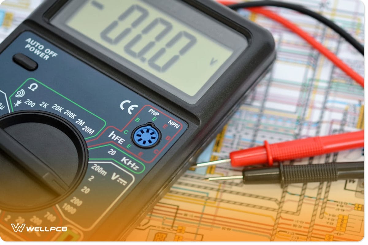
Digital Multimeter
How to Test a JFET?
We’ll discuss two methods we can use to test a JFET transistor. These methods include testing JFETs with a component tester and testing JFETs with a multimeter.
How to Test JFET with a Component Tester
This method is more straightforward than using a multimeter, and its results are accurate and quick. To do this, first, de-solder the JFET from the circuit and plug it into the component tester. Next, use the lever to connect and hold the JFET. Finally, press the button. It’s that easy.
So, if you have a working JFET, the component tester would display it and show some extra information about the transistor’s pins.
How to Test JFET with a Multimeter
Using only a multimeter won’t get you the accurate test results you need. So, to thoroughly test a JFET with a multimeter, you’ll have to build a small circuit that switches the device on/off. Thus allowing you to measure both on and off modes.
Also, you must know your pins. In other words, you should know what legs are: the gate, drain, and source.
Additionally, a JFET can stay on even when it’s not connected to the circuit. So, ensure the transistor is in off mode before you test it.
Once you’re sure the JFET is off, you can now use your multimeter to measure the transistor’s resistance. Make sure you set the device to a low ohms range so your readings can be accurate.
Finally, you should see something within the range of 100 to 130 ohms. But this depends on the actual transistor.
However, if your readings are high or you see the JFET is not conducting, you have a defective transistor.
Note: you can connect your JFET to a breadboard and also connect leads to make things easier.
How to Test a MOSFET
You must always test your MOSFETs before installing them in any circuit. Also, installing a defective power MOSFET can be harmful to your course. So, if you want to know more about testing a MOSFET, you can read it here.
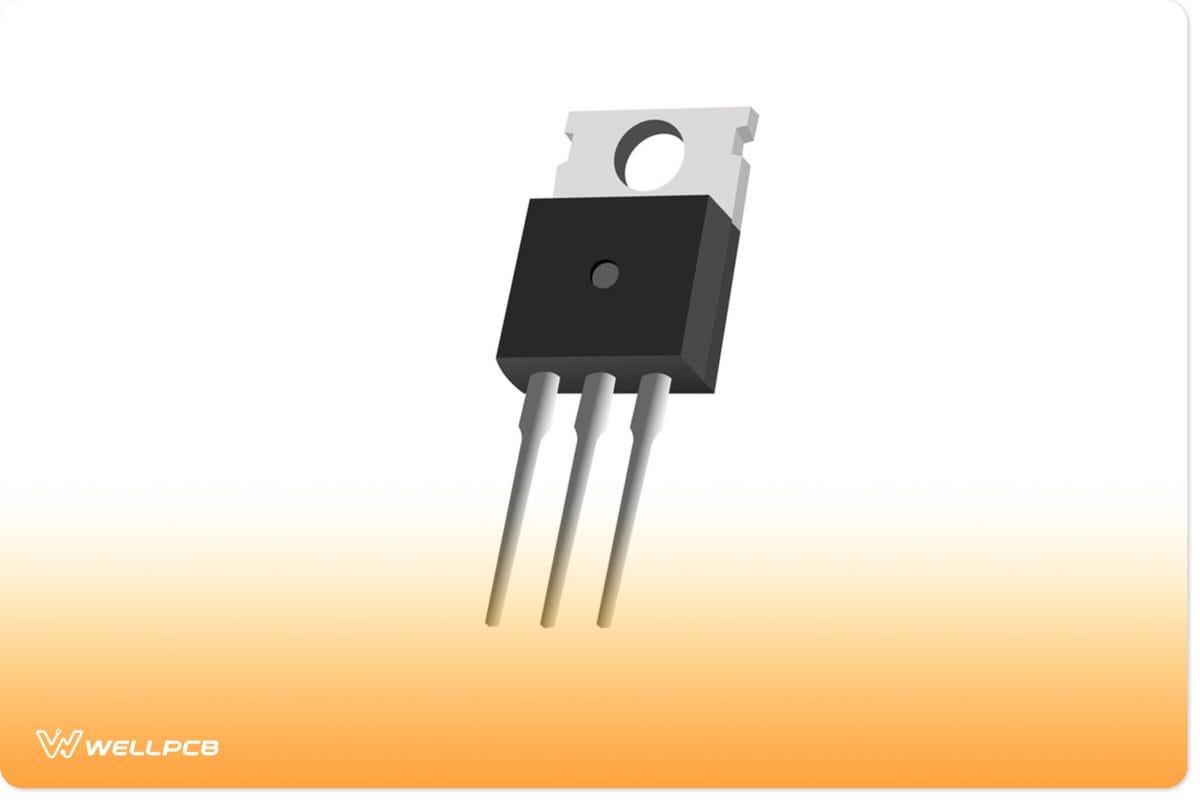
N-Channel MOSFET
Simple MOSFET Tester Jig Circuit
Students and technicians widely used MOSFET testers to measure transistors, solid-state diodes, and, of course, MOSFETs. With this circuit, you’ll know if a transistor or diode is working or defective. However, you won’t get the electrical parameters of what you measure from this tester.
With that out of the way, here are the components you need for this circuit:
- NE555 Timer IC (1)
- BC547 Transistor (1)
- 10 uF capacitor (1)
- 9V DC battery (1)
- 33k and 220-ohm Resistors (5)
- Battery Clip (1)
- 1N4007 diode (1)
- Female header pins (3)
- 45W-65W soldering iron and wires (1)
- 5mm, 3.5V LED (2)
- Veroboard (1)
- Jumper wire
Jumper wires
Steps to Follow
First, take your Veroboard and solder your NE555 timer. Afterward, connect one 33k ohm resistor between pins 2 and 3 and connect the header pins on the Veroboard. Also, don’t forget to solder.
Next, connect a 220 Ohm resistor between pins 3 and 8 and click the cathode of one 1N4007 diode to the anode pin of the other. Also, take the female header pin (collector), solder one anode-cathode junction to the first junction and connect the other corner to the 220 Ohm resistor.
Repeat the same anode-to-cathode connection with the LED and connect it with another female header pin (emitter). Also, attach the other junction to the anode to the cathode junction of the diode pair.
Also, connect a 220-ohm resistor between the diode junction (anode-cathode) and the base female header pin. Next, click the ten uF capacitor’s positive pin with pins 2 and 6 and the negative to the circuit’s GND. Following this, connect a 220 Ohm resistor between the female header emitter, female header base, and pin3.
Lastly, connect the battery clip to pins 4 and 8 and turn on the circuit with your 9V battery.
Wrapping Up
We mentioned how important it is to test your FETs, JFETs, and MOSFETs before using them in any circuit. Adding a lousy transistor to your course can cause a lot of damage to the circuit.
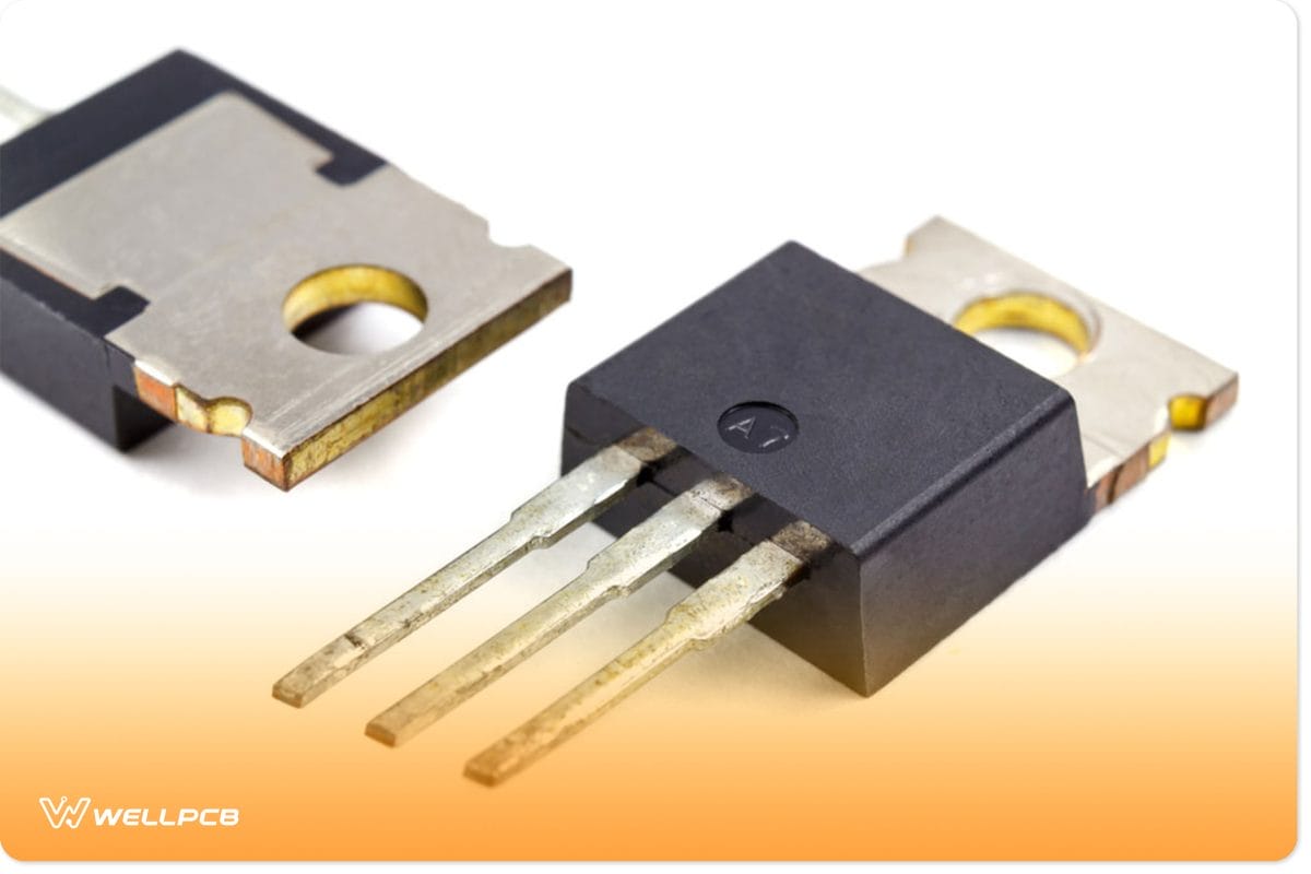
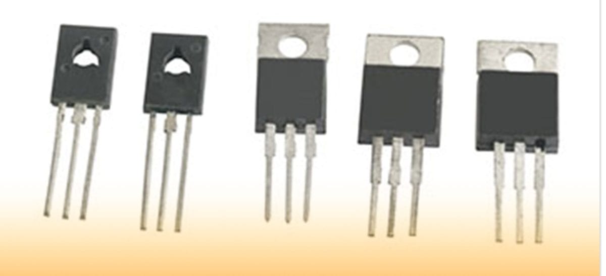
Power Transistors
Before we round up this article, there are some tips you should know when testing your FETs. First, check the various resistances of the multimeter to ensure you don’t need extra circuits. For JFETS from gate to source, if your multimeter indicates low resistance on both probes, it isn’t very accurate.
Lastly, the measurement of a MOSFET from the drain to the source should have infinite resistance, and getting a low resistance means you have a faulty MOSFET. Have any questions? Contact us, and we’ll respond in the shortest time possible. We’d love to help you.