Contents
What is a Heat Sensor Circuit?
The temperature sensor circuit exists within the heat sensor. It notifies one when the temperature increases and exceeds a particular value with the help of a flashing LED or a buzzer. We can say it works as a warning alarm device, e.g., in a smoke detector alarm.
A resistance temperature detector or a thermocouple uses an electrical signal to give centigrade temperature readings.
Temperature-sensing circuits are everywhere in today’s digital world, from computers to high-tech kitchen appliances. They are necessary since excessive heat has the potential to damage the expensive components in an electronic device. Heat sensors are also vital in improving security systems.
Therefore, how Does a Heat Sensor Circuit Work?
A simple temperature sensor circuit typically serves the purpose of sensing the heat around it. The functioning of the temperature meter depends on the output voltage that passes across the diode, meaning temperature change is directly proportional to the diode’s resistance. The higher the temperature is, the more excellent the opposition will be and vice versa.
You can adjust the threshold level using the variable resistor.
The diagram below represents a basic heat sensor circuit diagram that utilizes a Negative Temperature Coefficient type thermistor. The NTC is responsible for a decrease in resistance value when the temperature rises. This video has further information concerning the NTC and how to test it.
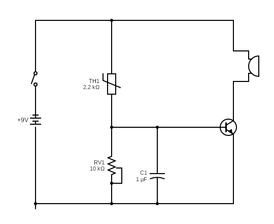
Heat sensor integrated circuit diagram.
The components in the circuit
- NTC thermistor 2.2KΩ
- Variable Resistor 10KΩ
- Transistor BC547 (NPN)
- Buzzer 9V
- Capacitor 1uF/16V
- 9V Battery
The transistor BC57 turns on the buzzer whenever the heat exceeds the set range of temperatures and turns it off when the heat falls below the limits.
The transistor’s base gets bias from the battery with the thermistor along with the variable resistor. The buzzer, on the other hand, connects to the output of the transistor.
The switch turns on the circuit.
Types and applications of the heat sensor
The heat sensor bases its two categories on its operation. They are;
- Rate of rising heat detectors
- Fixed temperature heat detectors
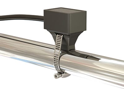
Fixed temperature heat detectors
This detector uses two heat-sensitive thermocouples and one monitors heat transfer by convection or radiation, and the other monitors heat from the environment.
The heat detector will operate regardless of the starting temperature, and the temperature rises from 12˚ to 15˚F per minute. If there is a possibility of determining the type of heat detector threshold value, we can operate the detector in low-temperature fire conditions.

a fixed temperature heat detector
Rate of rising heat detectors.
It does not respond to low heat release rates that deliberately start a fire.
It helps detect slowly developing fires due to its fixed temperature element that reacts whenever it reaches a threshold of 136.4˚F or 58˚C.

a rate of rising heat detector
There are various types of temperature sensors depending on their characteristics. A temperature sensor senses the heat coming from a system that allows us to feel physical change due to temperature coming from a digital or analog signal. the basic sensor types are;
contact temperature sensor types- it needs to be in physical contact with the object to detect liquid, solid, or gas over a wide range via conduction.
Non-contact Temperature Sensor Types– detects temperature change using radiation and convection. It can use infrared radiation to see the gas and liquid that radiates.
How do We Build a Primary Heat Sensor Circuit?
You can build a primary heat sensor that is effective. The items for making one are easy to access.
The first step is to get the parts ready. they are;
- Transistor BC547
- Diode 1N4148
- resistors (IEC)
- an NPN transistor
- a 9V battery for the power supply
- an LED lights
- Potentiometer (IEC)
You will also need a temperature detection circuit design to help in mapping out where the components go.

circuit design
The transistor BC547 will function as a heat sensor. As there is an increase in temperature of the p-n junction, the transistor starts partially conducting.
The Diode 1N4148 and 1k ohm variable resistor help set a threshold for heat sensitivity. You can rotate the knob if you want to adjust the sensitivity.
When temperature increases past the threshold level, the collector current increases, affecting the LED to start lighting slowly.
You should set the variable resistor before you start testing the circuit. Rotating the knob entirely in one direction will turn off the LED, and turning it to the opposite direction lights the LED. Hence set the potentiometer in a position where slight rotation starts illumination.
By using the below formula, we can understand the temperature dependence of p-n junctions in the transistor.
T = temperature in kelvins,
T0 = reference temperature,
VG0 = bandgap voltage at absolute zero,
VBE0 = junction voltage at temperature
T0 and current IC0,k = Boltzmann constant,
q = charge on an electron,
n = a device-dependent constant.
The junction voltage is a function of current density. We can obtain a similar voltage output by operating the two junctions at the same current.
Further information about this formula is available here.
The Base-Emitter voltage (VBE) drops by approximately -2.5 mV/°C. That means that there is a drop in voltage between B and E.
If we short the base, an NPN transistor will short (2) and collector (1), acting as a diode. In that case, 2 and 1 will serve as a positive terminal, while 3 acts as a negative terminal.
If we maintain the voltage source, the voltage will become the function of the temperature across the transistor.
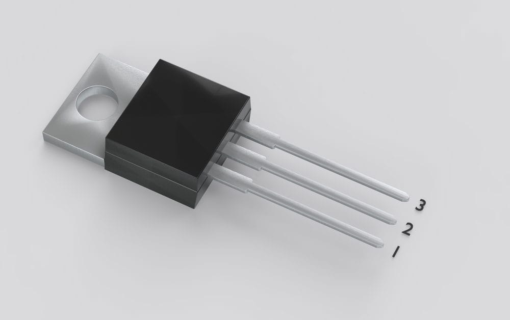
NPN transistor BC547 Pin configuration with 1- collector, 2- base, 3- emitter
The transistor BC547 has an operating temperature of up to 150 degrees Celsius, working at high temperatures as a heat sensor. This factor helps make effective fire alarms.
Advantages of Temperature Sensor
- Responds instantly
- It is more accurate
- Does not affect the medium
- It is easy to condition the output
Conclusion
In conclusion, hope you are now knowledgeable on how to make simple heat sensor integrated circuits. You can easily modify or add any component to your design to make it fit your needs. If you have any questions or comments, please feel free to contact us here.