Wireless communication is an exciting concept in this new age. Some, if not most, of the modern electronic devices use wireless communication in one way or another. This article will look at the HM-10 and its vital role in establishing wireless communication using the Bluetooth low energy module. Read through and get all the information you require to understand the HM-10, and the various necessary components are available here.
Contents
1. HM-10 Pin Configuration
The model design employs the CC2540 or CC2541 Bluetooth SOC (System on Chip) Bluetooth Low Energy (BLE).
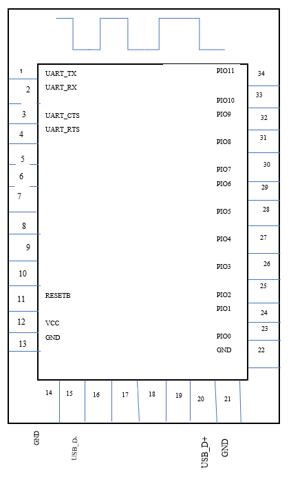
HM-10 Pin configuration
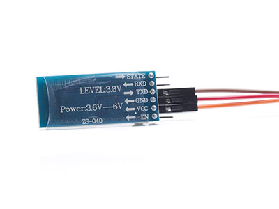
The HM-10 module has 34 pins, of which only four are necessary to establish communication.
| Pin no. | Pin Name | Pin Description |
| 1 | UART_TX | UART interface-Transmit |
| 2 | UART_RX | UART interface-Receive |
| 3 | UART_CTS | UART interface |
| 4 | UART_RTS | UART interface |
| 5-10 | NC | No Connection |
| 11 | RESET | Reset if low for 100ms |
| 12 | VCC | 3.3V |
| 13-14 | GND | Ground |
| 15 | USB_D- | USB interface |
| 16-19 | NC | No Connection |
| 20 | USB_D+ | USB interface |
| 21-22 | GND | Ground |
| 23 | PIO0 | System Key |
| 24 | PIO1 | System LED |
| 25-34 | PIO2-11 | Programmable input/output line |
The table above illustrates each pin and its function.
There are two versions of the HM-10 BLE Module, HM10C and HM-10S.
2. HM-10 Module Features
- No bytes limit while sending and receiving
- Bluetooth Low Energy consumption (BLE chip)
- Bluetooth version: V4.0
- Working frequency: 2.4GHz ISM band
- Use 50-200uA when the device is in sleep mode
- 12 General Purpose Input and Output Pins
- UART Serial Interface & Full-Speed USB Interface
- 32-kHz Sleep Timer with Capture
- In-Circuit Serial Programming 128 KB or 256KB
- 8 KB Static Random-Access Memory
- Long-range: Open space up to 100M
- Portable size
an easily portable Bluetooth module
2.1 The HM-10 Module specifications are:
- Operating voltage of MODULE: 2.0V – 3.6V
- Operates on LOW voltage
- 235uA backup battery consumption
- RF Input Level: 10dBm
- + 3.9V maximum voltage
- Operating temperatures of -40ºC to +85ºC
- Electrostatic discharge: 750V
The HM-11, HM-01, to HM-09 can also be used in place of the HM-10.
The HC-08 Bluetooth module
3. So, Where Can we Use the HM-10 MODULE?
- The HM-10 BLE Module is convenient for short-distance wireless communications of not more than 100 meters.
- Also convenient for a mobile device because of the low power consumption.
- The HM-10 Bluetooth 4.0 module is cheap, preferable for low-cost projects.
- It uses UART communication to connect to most controllers and processors, e.g., Arduino board.
Other applications include:
- Robotics
- USB dongles
- Servers
- Medical equipment
- Leisure and sporting equipment
- Computer peripherals
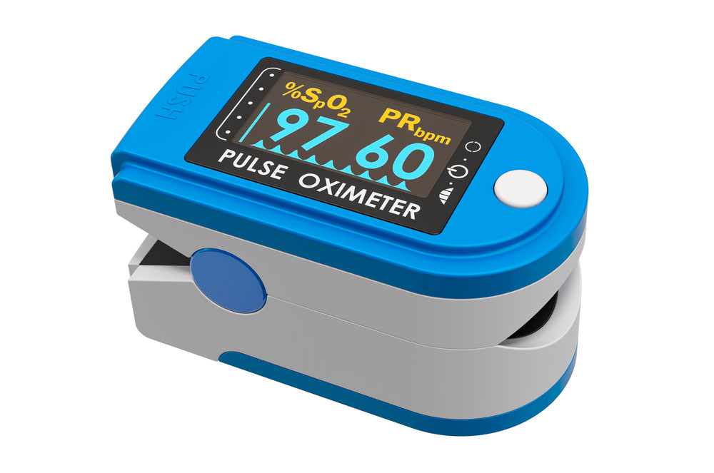
oximeter that uses a Bluetooth module

4. How To Use the HM-10 MODULE
The UART serial connection makes it easy to pair the module with an Arduino.
In case of problems, while integrating the Module with Arduino or Raspberry Pi, you can consult the HM-10 datasheet.
HM-10 Sensor on a baseboard
Ensuring your HM-10 module is genuine before using it on a project is vital.
Therefore, to avoid the cloned module, ensure yours has the 32KHz crystal oscillator.
Alternatively, you will need to change the module’s firmware version via a firmware download for a cloned module.
Otherwise, it will be impossible to access the Module with AT commands or pair it with a smartphone without changing the firmware.
The BLE modules can communicate with other BLE-capable devices such as an android device, i.e., 2 HM-10s.
Communication is possible through a serial UART and is fully customizable using AT command sets.
The module is a breakout board for CC2541 Bluetooth that includes a 3.3V power regulator.
Notably, when using the Arduino 5V board, the HM-10 RX pin is usually still at 3.3V. Hence it is necessary to convert the Arduino’s HM-10 TX pin to 3.3V.
4.1 Necessary components
- Arduino Bluetooth controller
- HM-10 Bluetooth module
- Resistors (1 kΩ, 470 Ω)
- Connecting wires (FTDI)
- Arduino IDE
- Android app- BLE Scanner (HM-10 Module)
4.2 Circuit Diagram

an HM-10 circuit image
source: https://www.youtube.com/watch?v=geSEbu6mj2Q
4.3 Arduino module setup + AT command
To execute the AT commands, open the Arduino board on your PC and ensure to select the correct USB port.
Next, open the serial monitors and confirm the default baud rate is at the factory default of 9600.
Then type in the command AT+NAME? Without spaces. it should show OK+NAME: HMSoft
You can now communicate with the Bluetooth 4.0 LE.
4.4 Sending and Receiving Data between 2 HM-10s
In this step, you can make 2 HM-10s send and receive data among themselves.
Use the AT command AT+ADDR? to Query the original MAC address.
The output will look like 20C38FF61DA1 remembering each HM-10 BLE has a unique address.
To pair 2 HM-10s use the command AT+CON[param1] and AT+ROLE[param1].
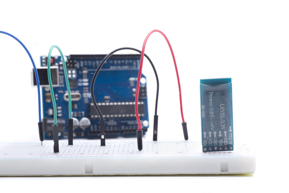
4.5 Wiring the HM-10 BLE 4.0 with Arduino board
Interfacing the Arduino Bluetooth controller with the module should connect as follows:
| HM-10 | Arduino |
| HM-10 TX | D2 |
| HN-10 RX | D3 |
| GND | GND |
| VCC | 3.3V |
You can either use the software serial or the hardware serial to program the Arduino UNO. In our sample project, we will use the software serial.

Arduino Bluetooth controller interfacing with the HM-10
Source:https://www.youtube.com/watch?v=Xt5e10B4Eq0&t=13s
The code below explains how you can control an LED using an Arduino Bluetooth controller and Bluetooth Low Energy.
#include <SoftwareSerial.h>
SoftwareSerial HM10(2, 3); // RX = 2, TX = 3
char appData;
String inData = “”;
void setup()
{
Serial.begin(9600);
Serial.println(“HM10 serial started at 9600”);
HM10.begin(9600); // set HM10 serial at 9600 baud rate
pinMode(13, OUTPUT); // onboard LED
digitalWrite(13, LOW); // switch OFF LED
}
void loop()
{
HM10.listen(); // listen the HM10 port
while (HM10.available() > 0) { // if HM10 sends something then read
appData = HM10.read();
inData = String(appData); // save the data in string format
Serial.write(appData);
}
if (Serial.available()) { // Read user input if available.
delay(10);
HM10.write(Serial.read());
}
if ( inData == “F”) {
Serial.println(“LED OFF”);
digitalWrite(13, LOW); // switch OFF LED
delay(500);
}
if ( inData == “N”) {
Serial.println(“LED ON”);
digitalWrite(13, HIGH); // switch OFF LED
delay(500);
digitalWrite(13, LOW); // switch OFF LEDs
delay(500);
}
}
4.6 BLE Android scanner app
To use an android device with the Bluetooth Low Energy module, you first need to download the BLE scanner for your mobile device.
Here is the link.
Once done, launch the app and grant Bluetooth and location permissions.
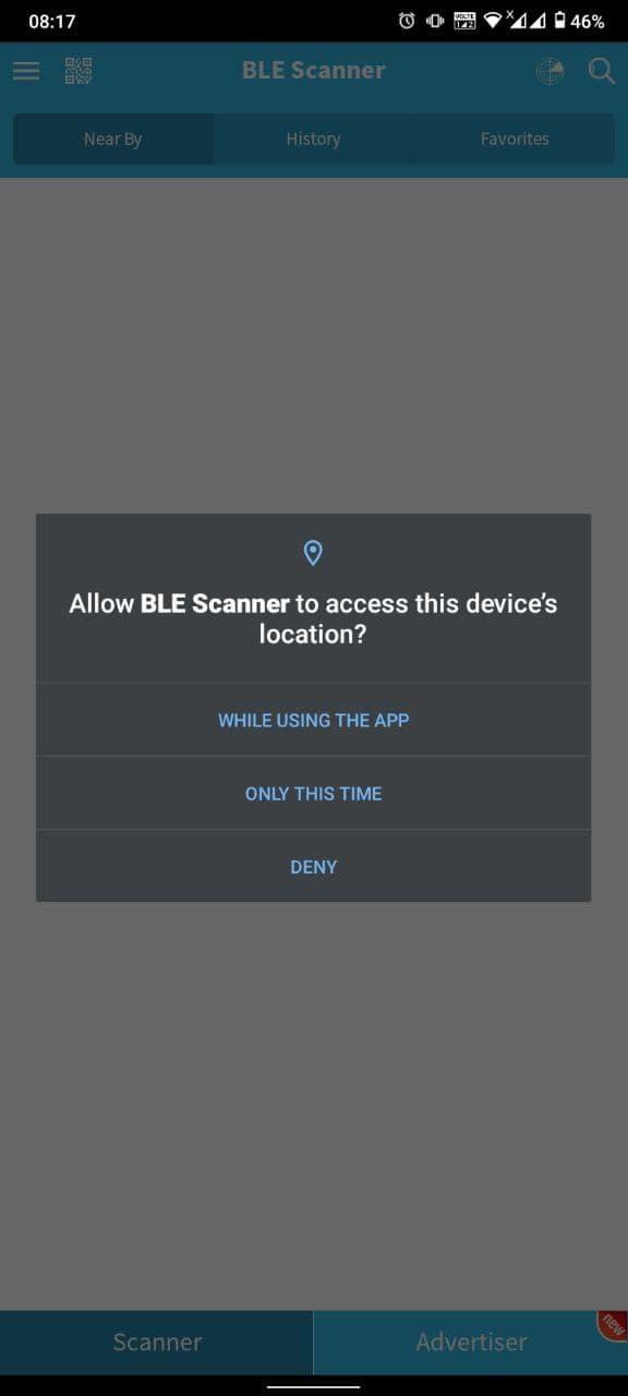
app permission page
source: app screenshot (https://play.google.com/store/apps/details?id=com.macdom.ble.blescanner&hl=en_IN)
Then scan for devices, the Bluetooth low energy 4.0 will be under MLT-BT05
Use 123456789 as the pairing code. Connect, and you are all set.
Once the connection is ready, click on MLT-BT05 for more options—select Custom Service.
Next, there will be options R, W, N.
For testing, click W to send1 or 0 to manipulate the LED with your android device.
5. How is the HM-10 BLE different from other modules?
The significant difference of the Bluetooth 4.0 LE to others is the Bluetooth version.
Remember that the default factory settings contain all the Bluetooth 4.0 features.
The default factory settings also allow it to transmit up to 24Mbps with low power consumption.
Therefore, when comparing the HM-10 to other modules, such as the Bluetooth 2/2.1, the HM-10 performs better.
The HC-05 module is among the modules that use Bluetooth 2.0.

The HC-05 module
Source: https://freesvg.org/1554744332
6. Conclusion
In summary, we have extensively looked at the features of the HM-10 module. Also, it is now easy to integrate Arduino in its default setting. With a baseboard and a few more components, you are now capable of conducting your project without a fuss. For more information, queries, or looking to purchase these components, contact us here.