Contents
What is a Rectifier?
Rectifiers are diodes that convert AC (alternating currents) to DC (direct current). In other words, rectifiers take an alternating voltage and transform it into direct voltage with high quality.
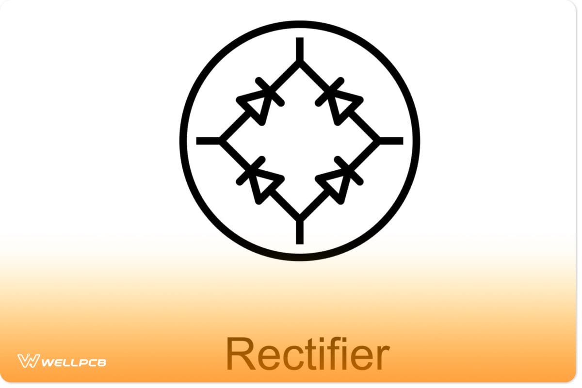
Full Bridge rectifier symbol
Alternating current has a regular reverse flow, while direct current moves in one direction only. Thus, the rectifiers correct the reverse flow of the AC and allow the current to flow in one direction, like the current generated by wind turbines.
Most telecommunication equipment needs DC Input power to work correctly. Nonetheless, such equipment usually runs off AC voltage as the main voltage source. Therefore, this equipment uses multiple rectifiers to turn AC into a DC power supply for operations. Plus, a rectifier is also applicable to an electronic device that needs DC power to operate.
Rectifiers are so important that using the wrong one could destroy your chances of configuring your desired system. The rectifier is like the heart of an electric power system. So, it helps you get the best solutions for each application. Thus, if you use rectifiers, you can easily configure your power system and get a suitable power rating – without rebuilding everything.
Types of Rectifiers
Now, we know that the rectifier is a crucial component when it comes to network systems. But first, we need to dive deeper to understand the type of rectifiers you need for your project. So, selecting the correct active rectifiers depends on the application—because rectifiers are conditional on the power devices you want to use or make.
Moreover, there are several categories of rectifiers grouped in pairs. Let’s take a look at these categories to understand what rectifier to use for your projects.
Half Wave and Full Wave Rectifiers
The half-wave rectifier is the most straightforward rectifier circuit to build. It only converts half the AC cycle of the AC input supply to the DC output voltage.
Plus, it allows only one-half cycle of the AC supply while blocking the other half. So, you can call this a half-wave rectification. Also, you can have either a positive or a negative half-cycle. The best part is that the half-wave rectifier only requires one rectifier diode.
Take a look at the diagram below:
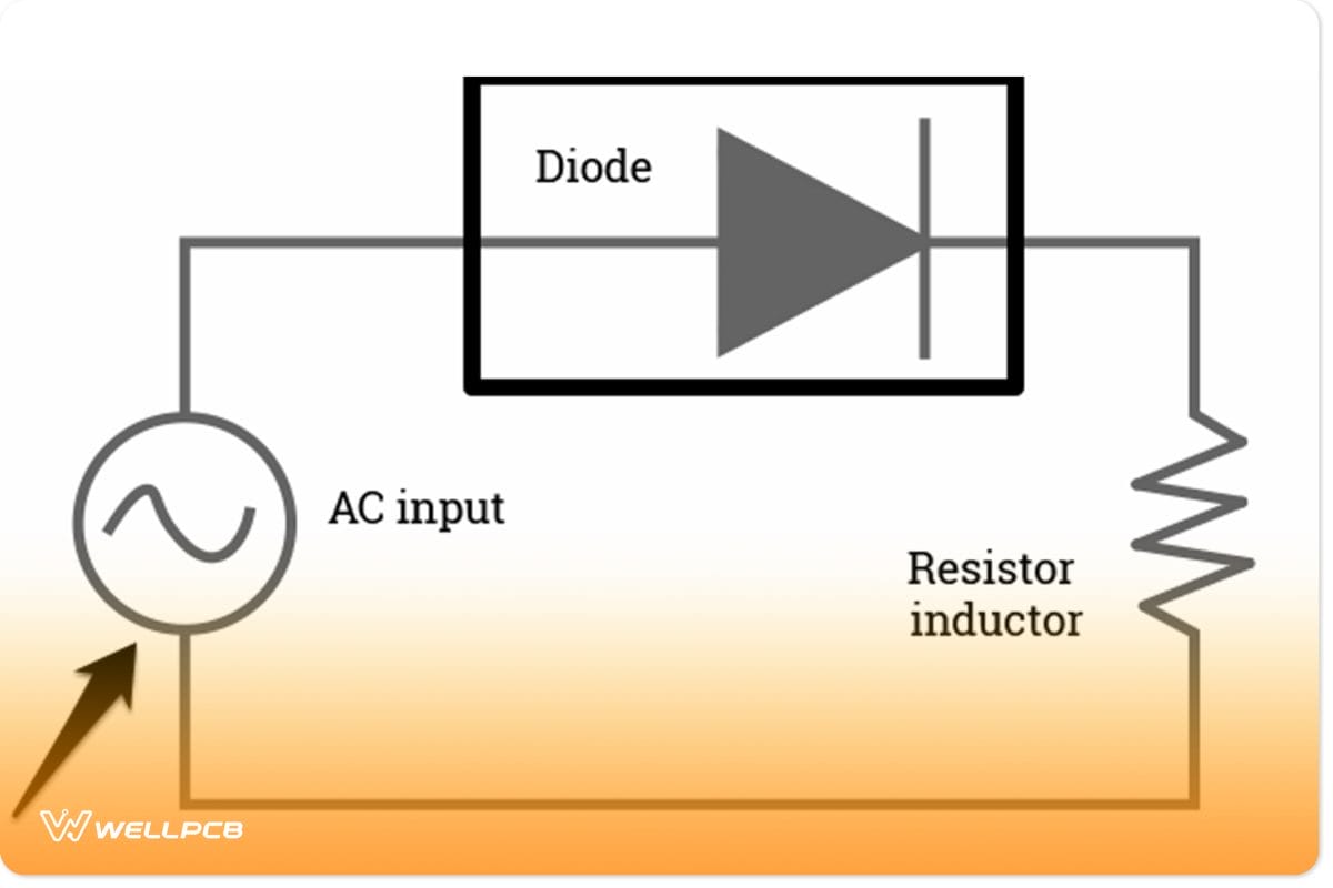
Half-wave rectifiers circuit diagram
This diagram shows positive half-wave bridge rectifiers with a high ripple factor. The ripple factor is high because of the voltage pulse of the direct current. Hence, half-wave rectification isn’t very efficient, as you’ll need filters to cut down the ripple factor.
Note: A negative half-wave rectifier would have its diode facing the opposite direction.
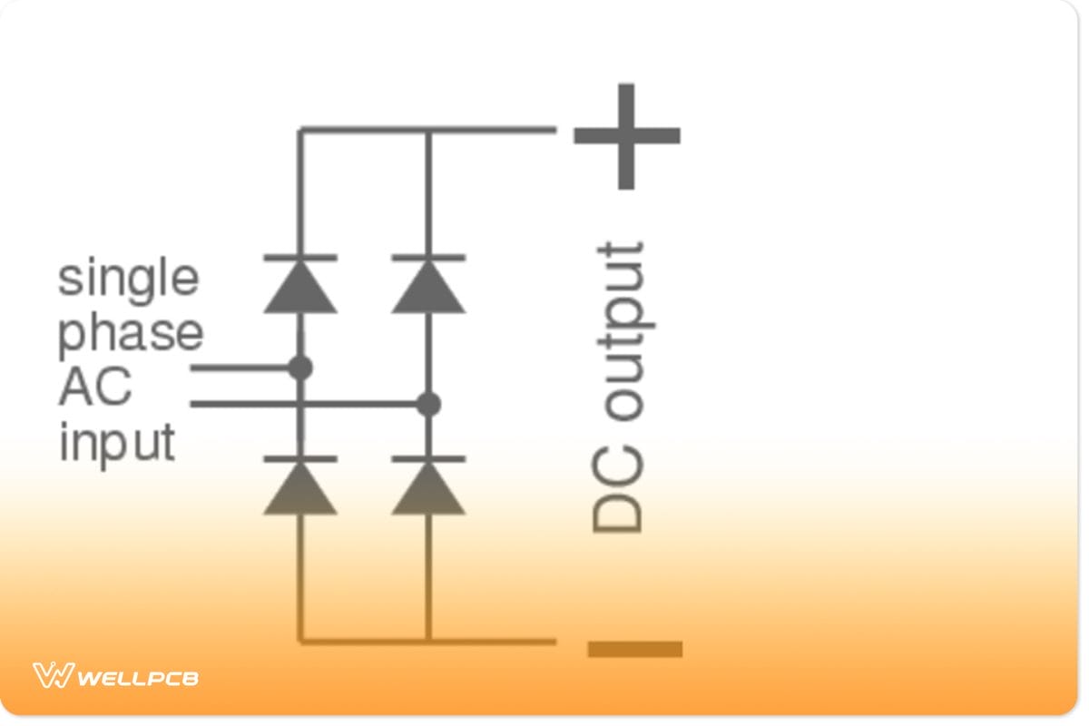
On the other hand, a full-wave rectifier converts the complete cycle (both positive cycle and negative cycle) of the AC supply voltage into pulsating DC output electric current. Thus, it’s called full-wave rectification. You will find that the full-wave rectifier circuit uses a center-tapped transformer—which connects over the middle of the transformer’s secondary winding.
Furthermore, the center-tapped transformer separates AC input into two sides: negative and positive voltage.
So, for this reason, the full-wave rectifier is much more efficient—as it has a lower ripple factor. Also, since you can convert both cycles, this circuit makes sure there are no wasted signals.
For example, take a look at the diagram below:

Full-wave rectifier diagram
Single-Phase and Three-Phase Bridge Rectifier
Single-phase rectifier circuits use an input of a single-phase AC power. It also has a simple structure that only requires one, two, or four diodes, depending on the system you’re building.
A single-phase semi-controlled rectifiers using bridge semiconductors
These rectifiers deliver only a tiny amount of reactive power with less transformer utilization factor.
Additionally, you can only connect the diode to the one-phase transformer secondary winding, which causes a high ripple voltage.
Like the single-phase rectifiers, three-phase bridge rectifiers accept input of three-phase AC power as their 3-phase voltage source.
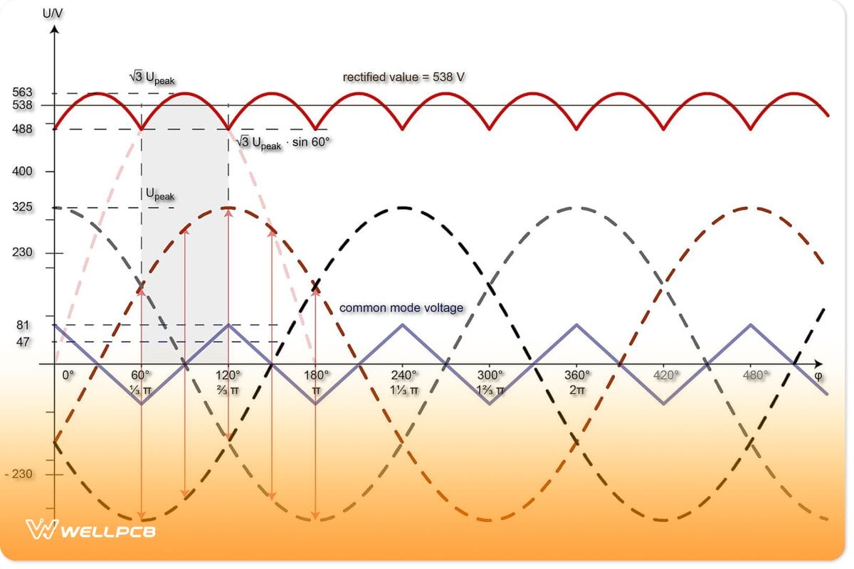
Such structures require three or six diodes for operations. Plus, you can connect the diode to each phase of the secondary winding—for the transformer. The three-phase bridge rectifier usually replaces single-phase rectifiers to control the ripple voltage of the output current.
Why?
Well, a three-phase bridge rectifier can deliver high amounts of power for large systems. Also, additional filters aren’t necessary to cut down the ripple factor.
Uncontrolled and Controlled Rectifiers
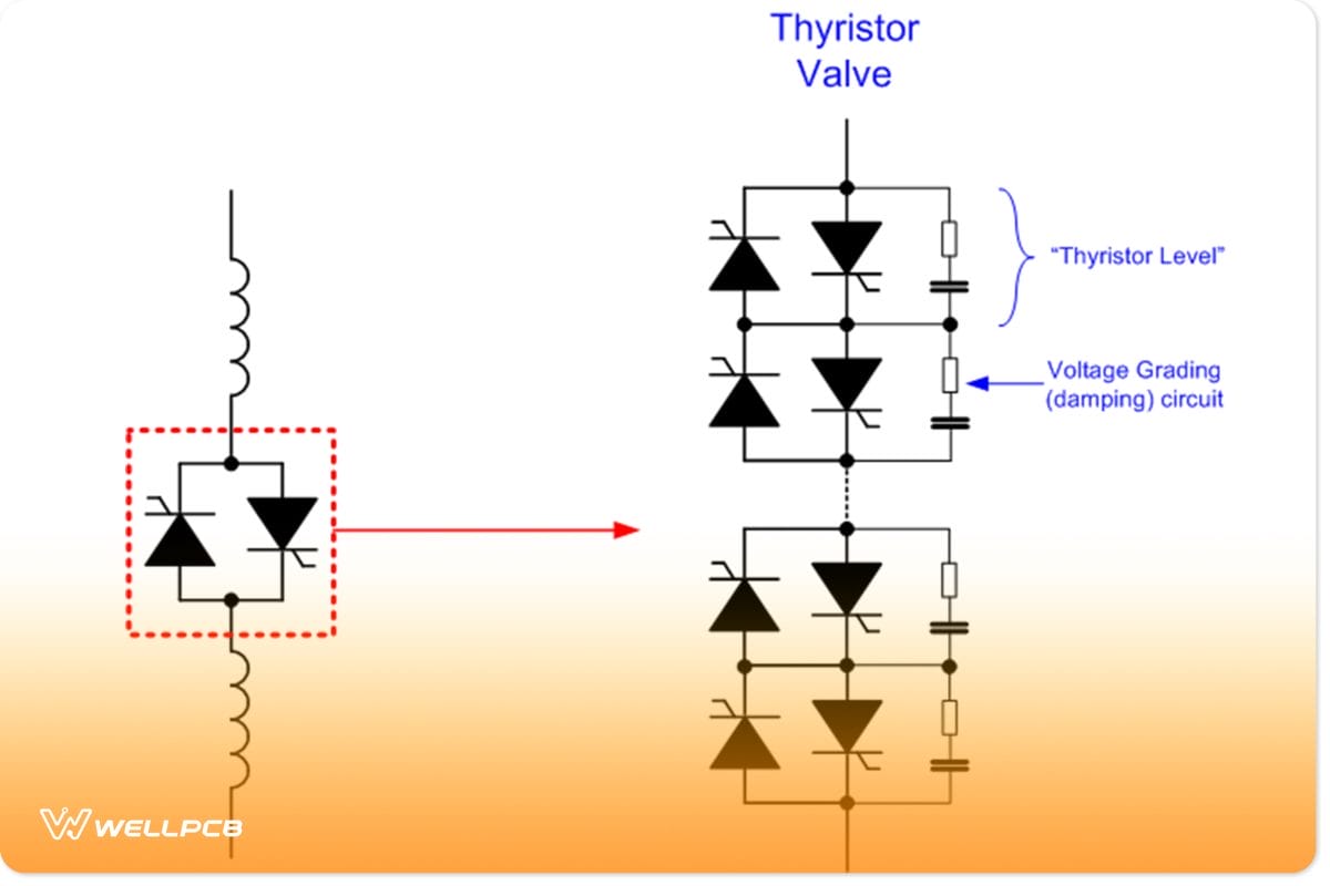
Controlled rectifiers using Thyristor bridge
Simply put, uncontrolled rectifiers use only diodes to convert power. On the other hand, controlled rectifier circuits equip thyristors to handle the DC output voltage of power devices.
Bridge Rectifiers
The standard bridge rectifiers are the most widely used rectifier circuit on this list.
Why? Because it does bridge rectification, a typical bridge rectifier circuit uses a load resistor and four or more diodes to supply direct current to the components of a power system.
The four diodes of the bridge rectifier are set in series, allowing the diodes to work in pairs. The first pair allows a good current level from the positive half-cycle, while the other provides current from the negative half-cycle.
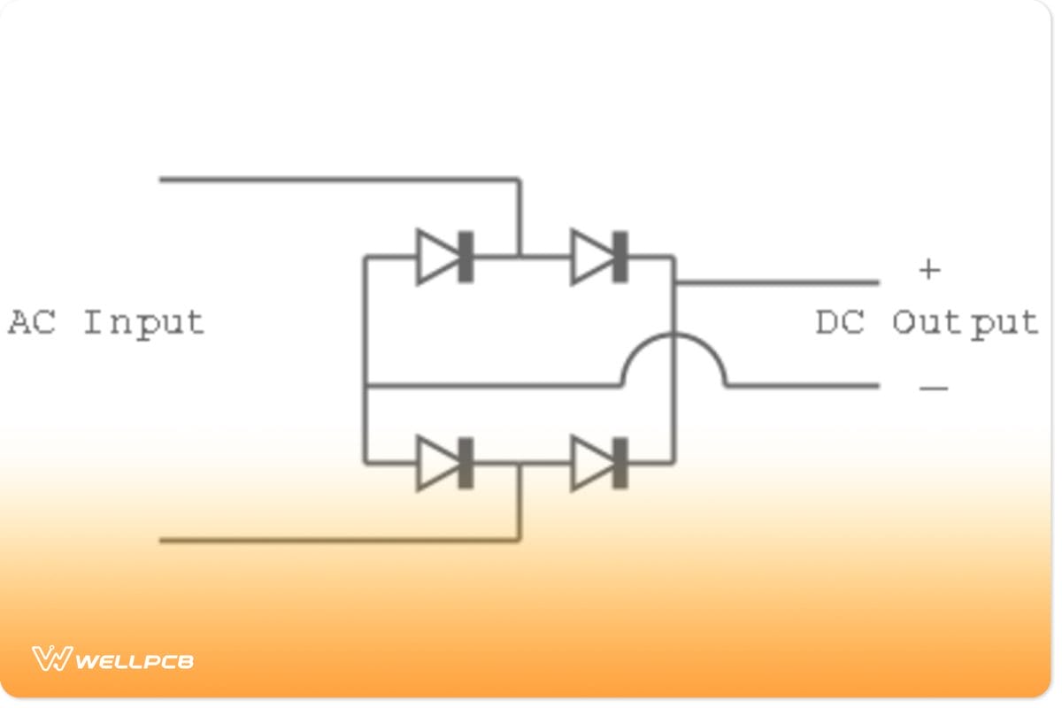
Diagram of Bridge Rectifiers
Note: bridge rectifier circuits do not work like half-wave rectifiers or three-phase rectifiers. Bridge rectifiers allow both positive voltage and negative voltage cycles of the AC input voltage. Plus, a center-tapped transformer is not necessary.
DIY Rectifier Circuit: How to Make a Rectifier?
As discussed earlier, there are different rectifier circuits, applications of rectifiers, and different current ratings.
So, we’ll show you how to make a bridge rectifier circuit.
It’s pretty easy to make a bridge rectifier circuit, and you can do it in three easy steps.
Here are the steps you need to make a simple bridge rectifier design:
Step 1: Gather your Materials
Here are the essential components you’ll need:
Jumpers (1)
1N4007 rectifiers diodes (4)
Any load of your choice (fan, gadget, LED, etc.)
Step 2: Bridge Configuration
The diode allows the current power source to flow in one direction while blocking the reverse direction.
So, to set up your diodes, you’ll need to:
- Select two of the four 1N4007 diodes and make an “L” shape with the cathodes of the two diodes (the ends with white bands).
- Do the same with the other two diodes above it, but this time, make an “L” shape with the anode of a diode (the ends with no bands).
- Connect the sets of the assembled diode bridges in a box shape, like in the diagram of the bridge rectifier above, to the positive terminal and negative terminal.
After assembling, you’d have a complete bridge rectifier.
Step 3: Examine and Test your Circuit
Make sure you connect the diodes properly. Also, ensure you click the DC output power wires to the DC and AC input wires to the AC. Lastly, check your simple bridge rectifier circuit to see if it works properly.
Closing Words
Well, that wraps up everything you need to know about how to make a rectifier.
In summary, rectifiers are an essential component when making a power system for your engineering project, especially when you need a positive output power.
Hopefully, we made things easier for you by listing out the different types of rectifiers. We also showed how to make the most widely used rectifier design.
Finally, here’s a small tip: always test the DC voltage output of your rectifier circuit with a digital multimeter before adding any load current.
If you need more information about the rectifier design and how to make one, feel free to contact us, and we’ll be happy to help.


