Contents
What is the PN532 Module?
The PN532 is a popular NFC RFID module that allows for mobile payments, Arduino NFC functionalities, and other smartphone communications. It is incorporated into modules that make pairing with your Arduino projects simple.
Additionally, it allows contactless communication at a 13.56 MHz frequency range and bidirectional speeds of 424 kbit/s.
PN532 NFC Module Pinout
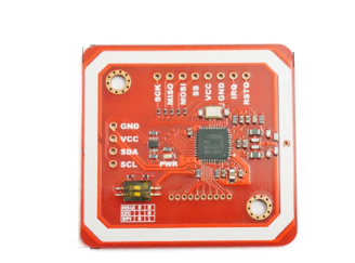
Fig 1: A PN532 NFC RFID module
The PN532 NFC RFID module supports I2C, SPI, and HSU communication modes. It uses the same pins for the I2C and HSU but separate ones for the SPI protocol.
Additionally, you can quickly tell the I2C pins at the module’s front. Furthermore, the HSU pins are at the back.
Here, let’s look at how each protocol’s pins:

PN532 NFC Module Features
- First, it has a microcontroller core with 80C51 architecture, 40 KB ROM, and 1 KB RAM.
- Second, it supports MIFARE ISO/IEC 14443.
- Third, it has a built-in RF-level detector.
- Fourth, it has a demodulator and decoder with high integration.
- Fifth, it supports up to 50mm operating range in Writer/Reader modes. Consequently, it allows smooth communication to FeliCa, ISO/IEC 14443B, or ISO/IEC 14443/MIFARE cards.
- Sixth, it has a 50mm maximum range in NFCIP based on power supply, tuning, and antenna size.
- Seventh, it has a 100mm operating range in FeliCa or ISO/IEC 14443A/MIFARE card emulation settings.
- Eight, it supports speeds higher than 424 kbit/s with external analog components.
- It has low power modes, programmable timers, a crystal oscillator, and a 2.7 to 5.5V power supply range.
Materials
- Arduino board
- PN532 NFC RFID module
- 15 connecting male-to-female jumper wires
- Breadboard
- OLED display (0.96” I2C OLED)
Interfacing PN532 with Arduino in I2C Mode
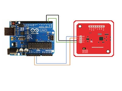
First, connect your Arduino with the PN532 module for I2C communication. That’s, connect ground to ground, SDA to A4, and SCL to A5, as shown below.
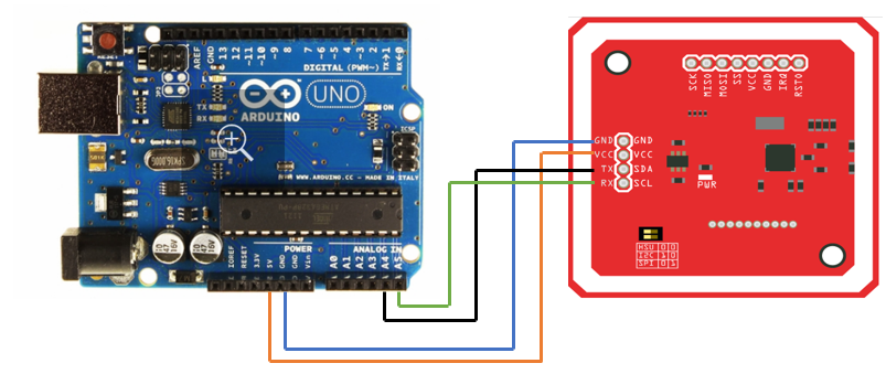
Fig 2: Connecting Arduino to PN532 module in I2C mode
Moreover, supply the board with 5V of electric power. You’ll then upload the following code to your Arduino setup.

After uploading the code, test the module by placing NFC cards close to the PN532.
Interfacing PN532 with Arduino in UART Mode
In this mode, connect ground to ground, Tx (clock) to D3, and Rx (data) to D2. Also, supply 5V of power through the Vcc pin.
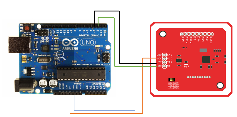
Fig 3: Connecting Arduino to PN532 module in UART mode
You’ll then find appropriate support libraries and add them to Arduino’s library folder. Afterward, please copy the code below and upload it to your Arduino board.


Lastly, open the Serial Monitor and test the module by placing NFC cards close to the PN532.
Interfacing PN532 with Arduino in SPI Mode
Connect the RST to pin 9, GND to GND, and MISO to pin 11. Also, connect MOSI to pin 12, SCK (Serial Clock) to pin 13, and SS (Slave Select) to pin 10.
Furthermore, add the PN532_SPI.h library to the Arduino IDE library folder.
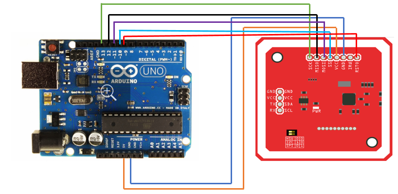
Fig 4: Connecting Arduino to PN532 module in SPI mode
Afterward, please copy the code below and upload it to your Arduino board.

Lastly, open the Serial Monitor and test the module by placing NFC cards close to the PN532.
Making a Portable NFC Scanner with OLED Display
Connect the OLED display and PN532 to Arduino as shown. GND to GND, SDA to A4, SCL to A5, and power the Vcc with 5V.
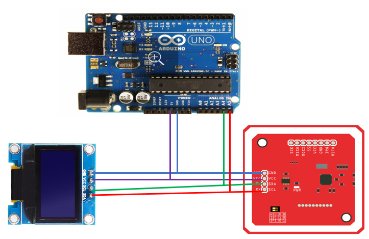
Fig 5: Connecting Arduino to PN532 module and OLED
You’ll then copy the code below and upload it to your Arduino board.


Lastly, test the PN532 module by bringing an NFC card close. The module will read and display byte length and UID value on the OLED.
Conclusion
Unlike other modules, the PN532 is beneficial as it uses protocols like I2C, UART, and SPI to communicate with Arduino. Additionally, it’s easy to set up, fun to work with, and cheap to acquire.
If you need help sourcing materials or getting through your project, contact us, and we’ll get back to you as soon as possible.


