
Suppose you intend to design a robot or a toy car, the knowledge about motors is paramount. A very cost-effective and easy way to control these motors is to use an L293D driver motor shield. Better still, use it in an interface with a microcontroller like Arduino.
Among the others, the L293D motor driver is one of the most popular chipsets of its kind. More so, for its diverse applications in electronic builds such as servos, stepper, and DC motors. However, its crucial attribute appears to be its direction and speed control in two independent DC motors. And that’s what you learn about further down this instructable.
Contents
1. What is the L293D Motor Driver?
This 16-pin chipset is a two-channel H-bridge driver for motors. Often, its primary function is as a controlling interface for DC motor pairs or in a single stepper motor.
By default, the L293D motor driver shield chipset comes in twos. Therefore, it is capable of driving four DC motors. For that reason, the L293D chipset is a valuable building asset in four-wheeled robots.
In total, the shield gives you four H-bridges. Therefore, each h-bridge delivers a motor current of 0.6A. Also, the 74HC595 shift register is a feature of the security. This register, as a result, extends the eight control pins of the dual L293D IC to the four-digit pins of the Arduino.
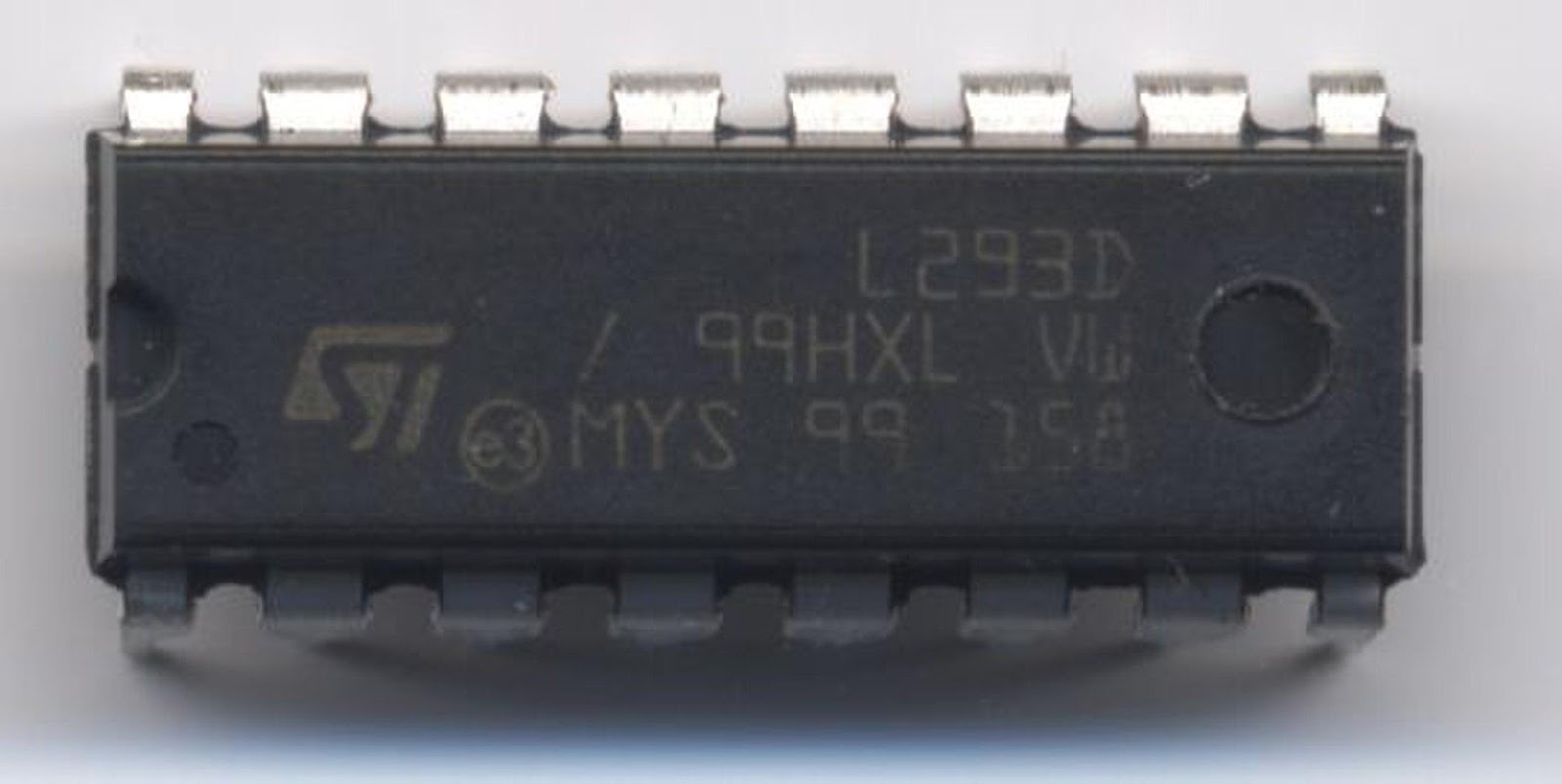
(A quadruple high-current H-bridge 16-pin L293D motor driver).
Source: Wikimedia
2. Features of l293D Motor Driver
Some features that make the L293D motor driver such a good component in CNC and robot projects include:
- It enables you to control the direction and speed levels in the applied device.
- More interestingly, the driver makes it possible to run two similar dual DC motors.
- The motor voltage, Vs. (Vcc2) is between 4.5V and 36V.
- Also, its max continuous motor current is 600mA.
- On the other hand, the max peak motor current is 1.2A.
- The Vss(Vcc1) supply voltage ranges between 4.5V and 7V.
- Transition time is at 300ns between 5V to 24V, at most.
- By thermal activation, it is possible to engage automatic shutdown.
- Finally, the IC is available in packages of SOIC, DIP, and TSSOP.
3.L293D Motor Driver Shield Output pin configuration
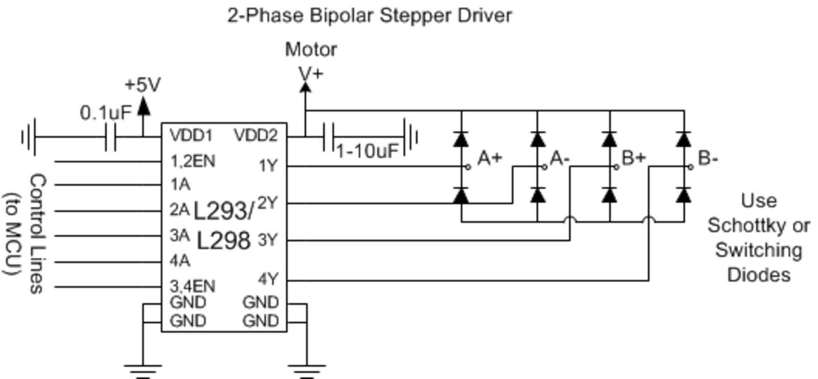
(A schematic pin diagram showing a bipolar L293D stepper motor driver).
Source: Wikimedia
| Pin Number | Name Of Pin | Pin Description |
| 1 | Enable 1,2 | This terminal activates the input pins: Input 1(2) and Input 2(7). |
| 2 | Input Pin 1 | It functions as a direct control for Output 1 pin. Often, you find it applicable in digital circuit control. |
| 3 | Output Pin 1 | This pin connects to one end, Motor 1. |
| 4 | Ground | On one end, this pin goes to the circuit’s ground (0V). |
| 5 | Ground | We have this other Ground pin (0V) on the other side. |
| 6 | Output Pin 2 | Like in Output Pin 1, this terminal connects to the other end of Motor 1. |
| 7 | Input Pin 2 | It directly controls the Output 2 pin. It is applicable in digital circuit controls, also. |
| 8 | Vs. (Vcc2) | With a 4.5V-36V rating, it connects to the voltage pin and supplies the motors. |
| 9 | Enable 3,4 | This terminal only enables the input pins: Input 3(10) and Input 4(15). |
| 10 | Input 3 | It offers direct control for the Output 3 pin. Additionally, it functions as another digital circuit control outlet. |
| 11 | Output 3 | This pin connects to one end of Motor 2. |
| 12 | Ground | Here, the Ground pin connects the ground of the circuit (0V) |
| 13 | Ground | Yet another Ground pin connected to the ground of the circuit (0V) |
| 14 | Output 4 | Like Output 3, this pin goes to the other end of Motor 2, as well. |
| 15 | Input 4 | On this end, it offers direct control for the Output 4 pin. It functions as a digital circuit control too. |
| 16 | Vss (Vcc2) | Finally, the pin connects to an external voltage of +5V responsible for supplying the IC. |
4. Working Principle of L293D Motor Driver
As highlighted earlier, the L293D motor driver can control dual DC motors. Hence, it’s essential to understand how this dual-channel H-bridge IC works.
(A diagram showing a 5-volt unipolar motor connected with an L293D).
Source: Wikimedia
The first stage of the working principle involves setting up an H-bridge. In other words, it uses double pairs of Darlington transistors we term Q2/Q3 and Q1/4. Across from each, a diode connects with the transistors’ collector and emitter. As a result, it prevents motor-generated back EMF from damaging the transistors.
So, when the transistors Q1/Q4 are in ON position, transistors Q2/Q3 goes off. Thus, there is current flow from Vcc, across the motor, and to the ground.
This action prompts a clockwise/counterclockwise direction spin of the motor. In summary, the motor polarity and the mode of connection to the power supply determine the spin direction.
On the other hand, when the Q1/Q4 transistors are OFF, Q2/Q3 switch ON automatically. Thus, there’s a reverse in the current flowing via the motor. So, when this reverse current flows, the direction of the motor’s rotation also alternates.

5. How Do We use the L293D Motor Driver?
As mentioned earlier, the L293D motor driver uses a bidirectional drive current of about 600mA and a range of 4.5V-36V. However, these features involve using this 16-pin motor driver chip with Arduino Uno.
Hence, we introduce a project that connects DC motors and L293D to ARDUINO. So, here is a stepwise procedure to set the circuit that controls DC motor direction and speed.
Step One: Assemble the materials you need for the project.
- Two 10K potentiometers.
- L293D motor driver chipset.
- Two small DC motors.
- Arduino Uno or Arduino Pro Mini.
- Breadboard.
- Jumper wires.
Step Two: Setting up the Circuit
The connections involved in this circuit are pretty straightforward.
However, we employ a video tutorial to set the circuit up for more precise illustration.
The motor is often better off with a different power supply altogether. In this case, we use 12V for the engine. On the other hand, a 5V supply powers the L293D and Arduino.
Note: The external power source goes to Pin 8 of the L293D. Take precautions while making these connections. Otherwise, you risk damage to the motors.
Step Three: The Code To Program a DC motor
We’re going to do that, and two basic steps are required.
Install AFMotor.h library.
First of all, we need a communication medium with the L293D IC. For that purpose, we have to install the AFMotor.h library.
This library enables us to issue commands that control DC, solenoid, and stepper motors.
To install the AFMotor.h library, first, scroll to Sketch. Then, find “Include Library,” after which you locate “Manage Libraries.” The library manager updates the installed library list as the library manager downloads the index.
Afterward, use the search filter to find ‘”Motor Shield.” Among the entries, select the Adafruit Motor Shield Library by Adafruit, then click on Install.
Run the Arduino Code
Next, we have to run the Arduino code below:
#include <AFMotor.h>
AF_DCMotor motor(4);
void setup()
{
//Set start speed for the motor & stop
motor.setSpeed(200);
motor.run(RELEASE);
}
void loop()
{
uint8_t i;
// Turn motor ON
motor.run(FORWARD);
// Accelerate from 0 to max speed
for (i=0; i<255; i++)
{
motor.setSpeed(i);
delay(10);
}
// Decelerate from max speed to 0
for (i=255; i!=0; i–)
{
motor.setSpeed(i);
delay(10);
}
// Then, alter the motor direction
motor.run(BACKWARD);
// Accelerate from 0 to max speed
for (i=0; i<255; i++)
{
motor.setSpeed(i);
delay(10);
}
// Decelerate from max speed to 0
for (i=255; i!=0; i–)
{
motor.setSpeed(i);
delay(10);
}
// Now turn motor OFF
motor.run(RELEASE);
delay(1000);
}
Step 4: Setup Complete
At this stage, your DIY circuit setup is complete. You now have a control mechanism for any DC motor device using this L293D chip and Arduino Uno microcontroller.
6.L293D Equivalent Dual Timer IC
Other ICs similar to L293D include ULN2003, SN754410, LB1909MC.
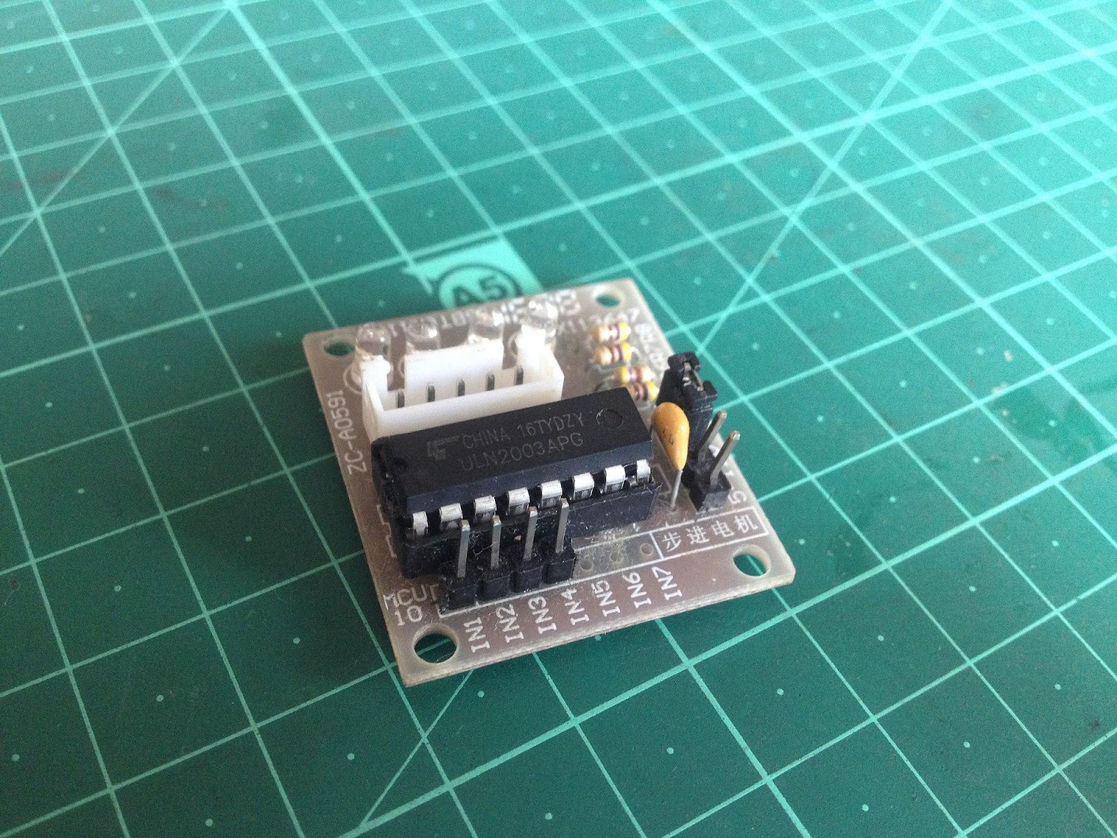
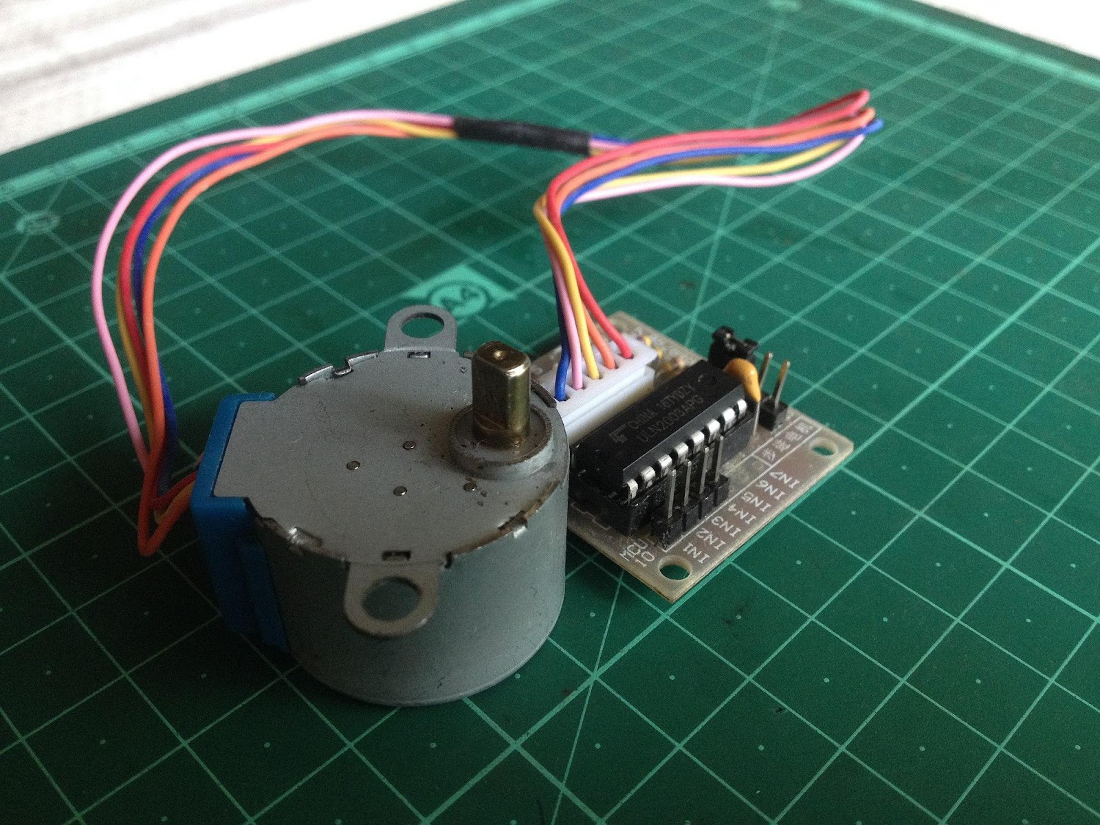
(A ULN2003 IC on a PCB showing the labeled pins and the connection points)
Source: Wikimedia
7. The Applications of L293D
- It helps you drive high-current LED devices.
- Also, it is applicable in high current motors operated by digital circuits such as robots.
- The L293D driver is an integral part of steppers and motors, in general.
- For use in relay driver modules. Hence, it makes a latching relay possible.
Summary
There are other different methods to control DC motors using Arduino in more ways than one. However, one of the easiest ways is to use an L293D motor driver IC. An L293D IC gives an edge for simultaneously controlling the speed and direction of two separate DC motors.
In conclusion, we have learned how to set up and program a DC motor with this IC. But, perhaps, you want to try your hands on something more challenging. For more tutorials on how to go about this, reach out on our contact page for complete guidance.


