Are you designing a power regulation strategy for your PCB? Or you’re working on creating a custom power supply for your board? If yes, it’s vital to reflect on the best way to control the power you send to your components. And this applies—especially if you’re dealing with high-speed digital systems. So, does power source matter? Whether you take power from a line voltage or battery—it’s pertinent to control the input power to the best level for your system. For instance, if you’re using power from a battery, an LDO circuit will be ideal. And it’s because the linear regulator provides adequate voltage. Plus, it offers a lower steady voltage from the input voltage.
That said, we’ll talk more about the LDO by highlighting its elements, working principles, applications, and more.
Let’s begin!
Contents
What is LDO?
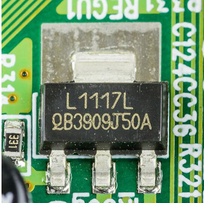
LDO is an acronym that means Low Dropout. You can also call it a saturation or low-loss type of linear regulator. And it functions at a low PD (potential difference) between input and output voltage supply.
The LDO regulator can only take input voltages that are a bit larger than the preferred output voltage. And it’s because the device is a step-down DC-DC converter with a variable input voltage. So, the dropout voltage refers to the least variance linking the input and preferred output voltage or power supply input.
Further, regardless of the device’s low power efficiency, it can operate stably with a low dropout voltage of ~1V. The linear voltage regulator can also offer different voltage levels with a stable and constant output.
Plus, the LDO’s output voltage is independent of the battery’s discharge, temperature, power loss, and load impedance. For instance, your Li-ion battery has an incoming power supply range of 2.7V to 4.2V. The 2.7V signifies a fully discharged battery, while the 4.7V is a fully charged battery. So, if your battery voltage reduces below 3V, the LDO can keep your output at 2.5V.
What are The Elements of the LDO Regulator?
The elements or key components of an LDO includes:
Error Amplifier
If you plan to design the LDO’s error amplifier, it’s vital to draw the lowest current possible. Why? Because the pass transistor’s gate capacitance is large. Hence, the amplifier’s output resistance should be very low.
Also, the error amplifier has two inputs. The first one is when the voltage divider scales the output voltage lower. Then, the reference voltage is next. So, when it finishes comparing both inputs, the error amplifier will modify the pass element’s resistance.
Pass Element
The error amplifier drives the pass element inside the feedback loop. And the pass element helps to move voltage into load from the input. Plus, you can use the NMOS and PMOS as pass elements.
When you take a close look at the circuit, you’ll notice that the Vo(s) connect to the V1(s). Further, the PMOS transistor needs a minimum voltage to regulate correctly and remains sodden.
And the least drain-source voltage V2(s) is responsible for giving the least voltage. But, it’s important to note that the PMOS pass element isn’t ideal for extremely low voltage devices.
Also, you can get a low dropout voltage, output, and input with the NMOS transistor. The pass element-based (NMOS) LDO benefit is that the regulator’s output resides in the transistor’s source. In addition, the NMOS enters the source follower configuration.
Voltage Reference
This element refers to any regulator’s starting point as it sets the error amplifier’s operating point. Also, you can use a band-gap type voltage reference—since it permits work at low supply voltages.
Output Capacitor
In the event of load transients, the output capacitor enables the LDO to move current inside the load—and the error amplifier becomes set.
Also, the capacitor’s ESR plays a huge role as it limits voltage flow moving into the load from the capacitor. So, if you’re working with a 1µF capacitor that has an ESR range (10 to 300m Ohms), you can use the following capacitor types:
- Low-ESR Tantalum Capacitors
- Ceramic Capacitors
- Polymer Electrolytic Capacitors
Feedback
This element helps you to scale down the output voltage. Plus, it permits the comparison between reference and output voltage using the error amplifier.
Features of The LDO
- The low-noise regulator can output a steady voltage. And it does this without being affected by the input voltage change. So, the LDO is perfect for supplying voltage to devices that are prone to noise.
- The device requires some external components (resistors or capacitors).
- LDO has a current limit function that protects systems from excess heat.
- LDO has an output discharge circuit that helps to discharge quickly and drop the output terminal voltage close to the IC GND.
- The device has a thermal shutdown function, and it helps to avoid destruction and deterioration.
How Does the LDO Work?
The LDO’s main components are the reference voltage source, pass element and error amplifier. And the pass element is either a P-channel FET or N-channel. So, it starts by applying the input voltage to the pass element (N-channel transistor).
Then, the transistor works in a linear region to decrease the input voltage. This process continues till the input voltage gets to the preferred output voltage. At this point, the error amplifier recognizes the resulting output voltage. Afterward, the error amplifier will compare the two parameters (output and reference voltage).
Also, the error amplifier will alter the FET’s gate to the correct operating point. Consequently, it helps to ensure that the output has an accurate voltage. Hence, the error amplifier will adjust the FET to have a constant output voltage when the input voltage changes.
What happens when the operating conditions are in a steady-state? Well, the LDO will act as a simple resistor. Plus, you can turn on or off the regulator with its Enable pin. This function helps users avoid battery usage—when the LDO isn’t in use.
When Do You Use an LDO?
- If you have a wide input voltage range, the LDO is ideal. However, it’s essential to consider getting a stable voltage output from the power supply. Also, you won’t need to adjust the PWM signal in the feedback loop. And it’s because the components don’t need feedback to the switching element.
- You can use an LDO when you need your system to have constant output power—regardless of the input voltage drop.
- The LDO is also useful for reducing the output to match the preferred output voltage.

Other Advanced LDO Circuits
An advanced LDO aims to give a user-selectable reference voltage. This function makes the device programmable.
Typically, the LDO can bypass high frequencies to ground. And it’s all thanks to the shunt capacitor diagonal to the output. But circuit designers pay more attention to filtering the output from a multi-stage regulator. Sadly, they don’t focus on input filtering.
Hence, you can boost your LDO with EMI filters. That way, your device will be EMC/CISPR compliant. Interestingly, this feature is crucial for producing higher-order harmonics with switching regulators.
Further, you can also add other necessary aspects to improve power distribution for your system (analog and digital).
Important Parameters to Select an LDO
Here are important parameters to consider before choosing an LDO:
Load Regulation
This parameter refers to the circuit’s ability to keep up a particular output voltage under different load conditions.
Load Regulation = ∆Vout/ ∆Iout
Quiescent Current
Quiescent is a state of dormancy. Hence, a Quiescent current is when a system draws current in standby mode. Also, this only happens when a battery connects to your device.
Transient Response
Transient response describes the highest permissible output voltage difference for a load current step change. You can also call the line step response. And this parameter is a function of the following:
Maximum load-current (Iout max)
ESR of the output capacitor
Output capacitor value (Cout)
Bypass Capacitor (Cb)
The equation of the transient response is:
∆Vtr, max = (Iout, max / Cout + Cb) ∆t1 + ∆VESR
Line Regulation
Line regulation is a circuit’s ability to retain a particular output voltage with different input voltage. And you can express it as:
Line Regulation = ∆Vout / ∆Vin
PSRR (Power Supply Rejection Ratio)
The PSSR of an LDO is when the device can discard AC elements. A good example of AC elements is ripple voltage. So, you can express it with the equation below:
PSRR (dB) = 20 log (Vripple (in)/ Vripple (out))
Applications of LDO Circuit
You can use the LDO circuit in the following applications:
- High-efficiency linear power supplies
- Computers
- SMPS post-regulator and DC/DC modules
- Wireless and wired communication
- Automobile application
- Battery-powered devices
- VPP regulation/ PCMCIA VCC
- Industrial application
- Digital core supply
Final Words
The LDO circuit plays a significant role in the electronics industry. After all, most power supplies require a linear regulator to get a preferred voltage. So, the device is ideal for projects that require constant output power regardless of the input voltage drop.
Also, you can reference the circuit diagram to understand the main components. What are your thoughts about the LDO regulators? Please feel free to reach us for more information.


