Contents
What is a Light Detector Circuit?
A light detector or sensor circuit is a device capable of detecting light intensity. Also, the device generates an output signal that shows the power of measured light.
Light sensors can measure the radiant energy present in every spectrum of light. Plus, it measures different frequencies of light ranging from:
- Infrared light
- Visible light
- Ultraviolet light
The light detector also converts light energy (visible or not) into electrical output signals. That said, you can also refer to light sensors as “photoelectric devices.”
What’s more?
Using a light sensor circuit’s electrical output to control other courses is possible. But, it’s crucial to have electrical load circuits or appliances like light bulbs, fans, or street lights.
Types of Light Sensors
Before building your light-detecting circuit, it’s key to know the ideal light sensor. There are two major categories of photoelectric devices. The first generates electricity when detecting light. In comparison, the second category can change some electric properties.
Hence, we have the following types of light sensors:
Photo-Emissive Cells
These photo devices generate free electrons from a light-sensitive material like cesium. A photo-emissive cell only generates electrons when hit by a proton with enough energy.
Also, the level of energy a proton has depends on its light intensity. Hence, the higher the power, the more energy a proton will convert light to electric energy.
Photovoltaic Cells
Sensors with photovoltaic cells can generate electrical energy equal to the light energy it receives.
Plus, two semiconductor materials joined together can receive light energy and create approximately 0.5v. Also, Selenium is a readily available photovoltaic cell that works in most solar cells.
Photo-Junction Devices
Photodiodes or phototransistors are typical examples of photo-junction devices. These devices use light intensity to control the flow of holes and electrons across their PN junction.
The design of the photo-junction devices works best for light detection and penetration applications. Plus, these devices only respond to the wavelength of incident length.
Photo-conductive Cells
Light sensors with photo-conductive cells don’t generate electricity. Instead, they change their physical properties when receiving light energy.
Also, the photoresistor is a common type of photoconductive sensor. And it changes electrical resistance according to changes in light intensity. In other words, photoresistors can use light energy to control electron flow and the current flowing through the electrons.
The Light Dependent Resistor (LDR) is another commonly used photoconductive sensor. LDRs can change their electrical resistance from thousands of Ohms to a few hundred in the presence of light.
How A Light Detector Circuit Works
When there’s an incident light on the LDR sensor, it gets a low resistance. Thus, the load connected to the circuit won’t get enough power to activate the device (i.e., keeping it in an off state).
So, when it’s dark, the LDR’s resistance increases to a level that allows current to flow through the circuit. As a result, the transistor activates. This helps to supply enough power to start the load.
Interestingly, you can reverse how the light detector works. That is, you can turn on the load when there’s an illumination and turn it off when there’s none. Plus, choosing how a light detector works depends on the application type.
Light Detecting Circuits Projects
In this section, you’ll learn how to build two types of light-detecting circuits. The first one is a light detector that uses LDR and OP-Amp. Then, the second circuit is a light detector using LDR and transistors.
Light Detector Using LDR and Op-Amp
The central feature of an LDR is how it changes its resistance depending on light intensity. Hence, this feature will be helpful in this project for detecting light and turning on an LED.
Plus, when the circuit couples with an Op-Amp in comparator mode–it helps to generate high or low output by comparing voltages. Here are the components you need for this circuit:
- LDR
- Connecting wires
- LM358 OP-Amp IC
- 10 KΩ Resistor
- White LED
- 9v Power Supply
- 10 KΩ Potentiometer
- 220 Ω Resistor
- Breadboard
Circuit Diagram
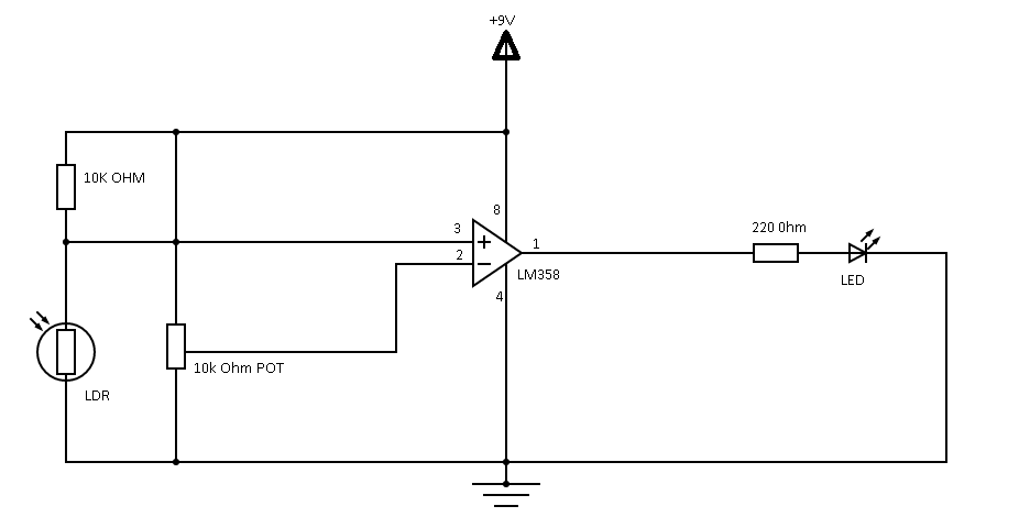
Circuit Diagram
How to Build
First, connect the 10 KΩ Potentiometer’s wiper terminal to the Op-Amp’s inverting terminal. Then, create a connection junction between the LDR and the 10 KΩ Resistor. As a result, you’ll create a potential divider that feeds the output to the OP-Amp.
Also, create a connection between the white LED and the 220 Ω Resistor. Then, connect your 9v power supply to the circuit and test to see if it works.
When you shine some light on the LDR, it should decrease its resistance. And the inverting voltage will be higher than the non-inverting voltage, which keeps the LED off.
If there’s no incident light on the LDR, it would have a higher resistance. As a result, the inverting voltage will be lower than the non-inverting voltage. Thus, the OP-Amp’s output will be increased and turn on the LED.
Light Detector Using LDR and Transistors
If you don’t have an OP-Amp to build the previous circuit, you can use a transistor instead. Here, a single transistor will carry out the light detection operation.
So, you can use a Darlington pair for a more guaranteed output current. But in most cases, a single transistor will suffice. Here are the components you need for this circuit:
- BC547 NPN Transistors
- Connecting wires
- White LED
- 9v Power Supply
- 10k Ohm resistor
- 470 Ohm Resistor
- Breadboard
Circuit Diagram
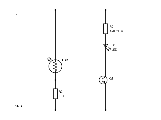
Circuit Diagram
How to Build
First, connect your LDR to the Breadboard and your transistor’s base to one of the LDR’s pins.
Then, connect your LED to parallel pins on the other end of the Breadboard. Next, you should secure your 470-ohm resistor to the LED’s positive terminal (+ve) and the Breadboard’s positive rail.
Connect your 10k resistor to the transistor’s base and the Breadboard’s negative rail (-ve). Next, join some jumpers between the Breadboard’s negative rail and the transistor’s emitter.
Lastly, connect your 9v power supply (preferably a 9v battery) to the Breadboard and test your circuit.
How it Works
The project works with three conditions: whole light, medium light, and no light.
For the complete light condition, any bright illumination on the LDR would reduce its resistance–resulting in a dim glow from the LED. So, in a medium-light condition, a medium-level description of the LDR would result in a medium glow.
Also, in a no-light condition, the LDR’s resistance increases. Hence, it generates a bright glow on the LED. Plus, you can regulate the LED’s brightness by adjusting the resistor connected to the transistor’s base.
Applications of the Light Sensor Circuit
Light sensors work in different applications like security alarm systems, high-sensitive power savers for street lights, control systems for home lighting, and a solar highway lighting system (for automatic turn-off in the daytime).
Other applications include automatic switching for appliances and lighting systems for cupboards and wardrobes.
Sunset to Sunrise Lighting Switch
STS lighting switches use light sensor circuits to control their load based on the incident light on the LDR. And the STS lighting switch works differently from the other applications and projects listed here. So, instead of transistors or an OP-Amp, the STS lighting switch uses a 555 timer IC in the bistable mode.
When you illuminate the LDR, it sends output to the 555 timer IC, which uses a TRIAC to control the load. Then, the sensor will activate the gear during sunset and start it during sunrise.
Rounding Up
The light sensor circuit is a versatile and easy project in basic electronics. We’ve extensively discussed how different LDRs work and showed you the components needed to get things running. Therefore, you can try your hands on the project right away.
Interestingly, you can use an LDR with an OP-Amp, transistors, and 555 timer IC.
Do you have any questions or suggestions about the topic? Not to worry, you can always reach out to us, and we’ll be more than happy to help.


