An LM338 integrated circuit is part of the LM-series ICs made by the National semiconductor. LM338 application circuit is similar to LM350 or LM317 in terms of easy usage and few components. However, LM317 has a lower current than LM338. In today’s post, we’ll discuss an IC LM338 circuit based on its characteristics, applications, pin configuration, to mention a few.
Contents
What is lm338 IC?
Also, it is easy to use since it only needs two resistors to set the output voltage. Moreover, its load and line regulation circuit design make it exceptionally reliable compared to other commercial power supplies.
Note;
- Even though capacitors aren’t necessary, 6 inches/150 mm from the input filter capacitors will require an input bypass capacitor.
- Additionally, you can include an optional output capacitor to enhance transient response.
- Lastly, you can bypass the regulator’s adjustment terminal to create high ripple rejection.

(Electronic integrated circuit chip)
LM338 IC pin Arrangement and Configuration
The configuration of LM338 IC has a pinout arrangement with three terminals. The terminals are;
Pin2/ Input pin: It receives DC signals.
Pin1/ Adjust pin: Sets/ adjusts the desired output voltage.
Pin3/Output pin: It generates the output voltage, filters it via the filter capacitor then sends it to the circuit’s Output.
Characteristics and Applications of LM338 IC
A couple of LM338 IC features include;
- Adjustable output ranging from 1.2 volts to 37V,
- A short-circuit protected output,
- Specified 5A output current,
- Line regulation typically 0.005% /V,
- P+ – product enhancement tested,
- Specified thermal regulation,
- Load regulation at 0.1%,
- A standard 3-lead transistor package,
- Specified 7A peak/maximum output current, and
- A current limit is constant with temperature.
Further, an LM338 IC has the following applications;
- Battery chargers,

(battery chargers).
- Adjustable power supplies, and
- Constant current regulators.

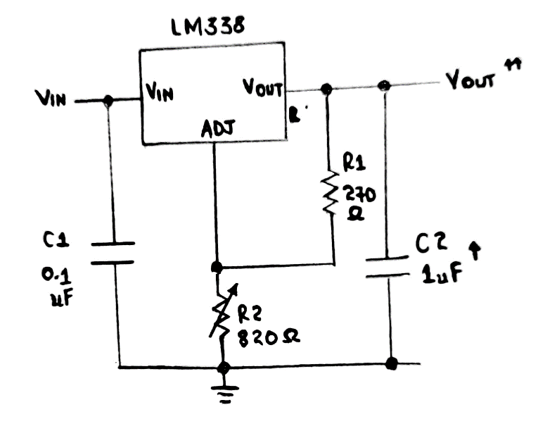
LM338 Basic Circuit Voltage Calculator
Now, let us observe the LM338 application circuit below. You’ll only need two resistors to set a constant output voltage, and a voltage regulator calculator varies the value of output voltage set R2 and program R1.
Therefore, the calculation in finding the output voltage for the IC LM388 incorporates a formula;
Vout = 1.2V × {1 + R2/R1} + ladj × R2
Ladj sometimes has a low current of approximately 50uA. In that case, a shorter formula is recommendable; Vout = 1.2V × {1 + R2/R1}.
LM338 IC work schematic
The schematic diagram of an LM338 has several electronic components such as external capacitors, transistors, resistors, and Zener diodes.

A schematic diagram of LM338 IC
120 ohms suits R1 for the IC LM338 regulator. However, you can also use values like 220 ohms or 150 ohms for R1. In addition, you can configure the LM338 voltage regulator to control the circuit current.
- LM338 application circuit
The next session will tackle practical examples of IC LM338 application and power supply circuits. They are easy to apply thus, being efficient for both beginners and professionals.
Using a single control to adjust many LM338 modules
Description; You can use a single pot to control several modules of the LM388 circuit as per the diagram below.
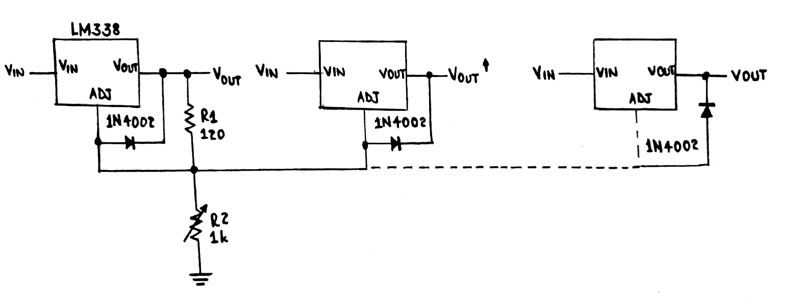
A circuit diagram of many IC LM338 modules using a single control
LM388 circuit as a light controller circuit
You can also use LM388 as a light controller.
As for the diagram, the phototransistor replaces the standard resistor that adjusts the output voltage. Moreover, the IC output powers the light that you need to control before allowing it to fall on the phototransistor.
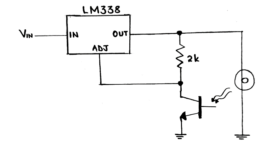
A light controller circuit
Then, an increase in light causes a decrease in the phototransistor value. In turn, the value drop pulls the IC’s Adj pin further towards the ground. That causes a reduction in output voltage and the light illumination, hence sustaining a constant lamp glow.
A heater controller circuit
You can configure an IC LM388 to control the temperature of many parameters, such as a heater. You’ll need another integrated circuit (an IC LM334) as a sensor for the circuit diagram. Connect the IC LM334 ground of IC LM338 and crossway the Adj pin.
A heater controller circuit
As the heat from the source gradually increases more than the prescribed threshold, the sensor LM334 lessens its resistance. Subsequently, the LM338 output voltage drops therefore reducing the heater element voltage.
A simple 13V 5A adjustable voltage LM338 power supply circuit
The application here is a simple circuit format that involves an IC LM338.
The circuit has an adjustable output ranging from 1.2/1.25V to a maximum input voltage of less than 37V.
- Resistor R2 varies the output voltage uninterruptedly.
- Furthermore, diodes D3 and D2 function as protection diodes.
- T1 is the primary transformer with 230V.
- Then, you can use the VR potentiometer connected to the Adj (adjustment pin) to change the output voltage.
- C3 and C2 are the decoupling capacitors, while C5 and C1 are filter capacitors.
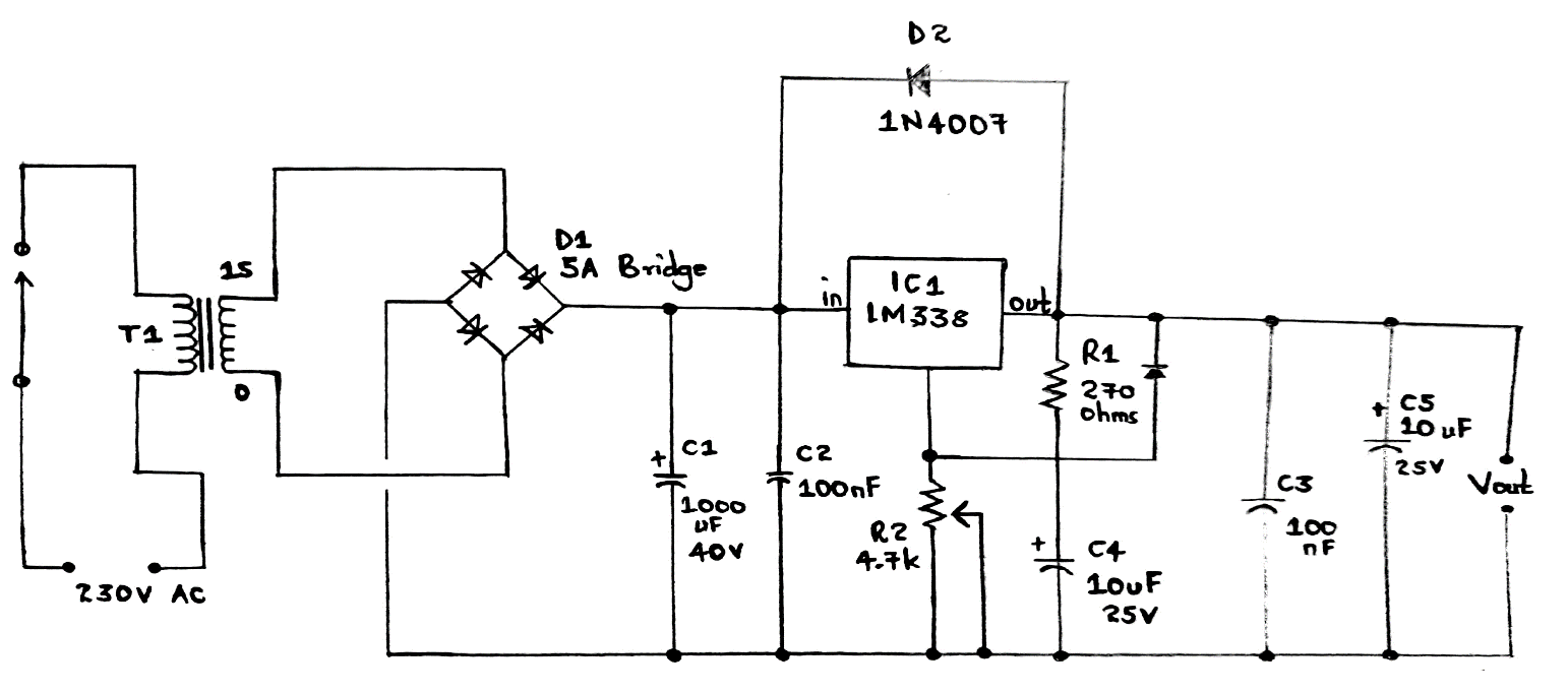
A 13V 5A adjustable voltage LM338 circuit diagram
Working principle
The circuit uses the process below to operate.
- The transformer steps down the voltage from the 230V AC to 15V.
- The voltage then passes through the diode bridge rectifier and becomes a DC Ripple.
- Before getting to the IC LM338, the DC signal passes through the noise filtering capacitor.
- In the capacitor, the signal goes through pin2, pin1, and finally pin3 to give a total output to the circuit.
A few tips you should consider when setting up the circuit are;
- First, fit a heat sink into IC LM338 when connecting it to prevent damage to the output transistor and overheating.
- Secondly, you can use switch S1 as an OFF/ON switch.
- The 5A diodes and 8A transformer can make this DIY project a bit expensive. And so, only set it up when necessary.
- Again, if you can’t find a 5A bridge diode, you can make one with diodes, an example being SR520.
- If needed, you can connect an optional 6A fuse in series with the +ve output terminal.
A battery charger circuit with 12V current control
The circuit diagram below uses a 12V lead-acid battery as the charger. Thus, ensure you select appropriate resistors (R1 and R2) to determine the desired current level of the 12V battery.

Circuit diagram of a battery charger circuit with 12V current controller
You can further adjust resistor R2 to obtain other voltages when charging different batteries.
Summary
To conclude, LM338 IC is a reliable component for electronic devices because of its thermal regulation, 3-lead transistor packaging. Other than that, it also has a time-dependent current limiting.
Our detailed article gives you an overview of what yoyou’llncounter in an IC LM338 datasheet. What’s more, we discuss several LM338 application circuits that you may create.
Still in the dark about LM338 IC technology? Kindly contact us for more assistance.


