
Contents
What is an Ultrasonic Sensor?
Ultrasound describes a sound wave that is a frequency beyond the range of human hearing. As such, it makes it a great candidate for synthetic echolocation.
Much like hypersonic sound systems, ultrasonic sensors function on this principle by emitting sound waves. These sound waves will then bounce off objects and return to the sensor. Subsequently, the sensor will then calculate the distance by measuring the travel time and speed of sound from its base to the object.
Thus, simply put, ultrasonic sensors are essentially a cost-effective and reliable way to measure and detect object presence and the distance between objects. They function as a middle ground between the proximity sensor and the laser distance sensor in range and cost. Essentially, ultrasonic sensors cover a greater distance than proximity sensors but a shorter distance than laser distance sensors.

The doctor holding a transvaginal ultrasound wand
Applications and Key Benefits of Ultrasonic Sensors
Here is a summary of some of the advantages and uses of ultrasonic sensors:
- They can detect small objects over great distances (50mm to 3.5m)
- Their measurement and detection capabilities are indiscriminate of a target’s surface and texture
- Ultrasonic sensors are great for the detection and measurement of:
- Solid materials such as metal, wood, plastic, paper, cork, glass, etc.
- Rolled goods such as tissue and textiles
- Bulk goods such as sugar, flour, potatoes, etc.
- Liquids such as water, oil, juice, etc
- They are ideal for healthcare applications such as pregnancy scans
- We can use them in collision detection systems for cars
- Ultrasonic sensors are independent of the target’s color
- They are independent of environmental noise, light levels, and temperature swings
- Ultrasonic sensors are independent of steam, fog, dust, and high humidity
- They are solid-state – they have an almost unlimited and maintenance-free lifespan
Ultrasonic Sensor Types
We can break ultrasonic sensors into three groups or types:
- Object detection: These types of ultrasonic sensors only have discrete on/off outputs.
- Distance measuring (ultrasonic distance sensor): These ultrasonic sensors use travel time to determine the distance between objects. They only have an analog output.
- Combined type: these types of ultrasonic sensors have both object detection and distance measurement capabilities
In most cases, there’s only a 15% price difference between a sensor that has both capabilities and the least expensive minimal sensor. Nevertheless, choosing the ideal sensor can be a little overwhelming with all the available options.
That’s why it’s good to understand all the available specifications and parameters (output, diameter, distance, etc.)
How to Make An Ultrasonic Sensor Circuit
In this section of the guide, we’ll explore how to create and work with your very own ultrasonic sensor.
Components and Materials
- Solderless 400-point circuit breadboard
- 6 x jumper wires
- Arduino Mega 2560 REV3
- HC-SR04 Ultrasonic Sensor
- Tape measure
You’ll also need a computer and some working knowledge of the Arduino IDE.
Prerequisite Information
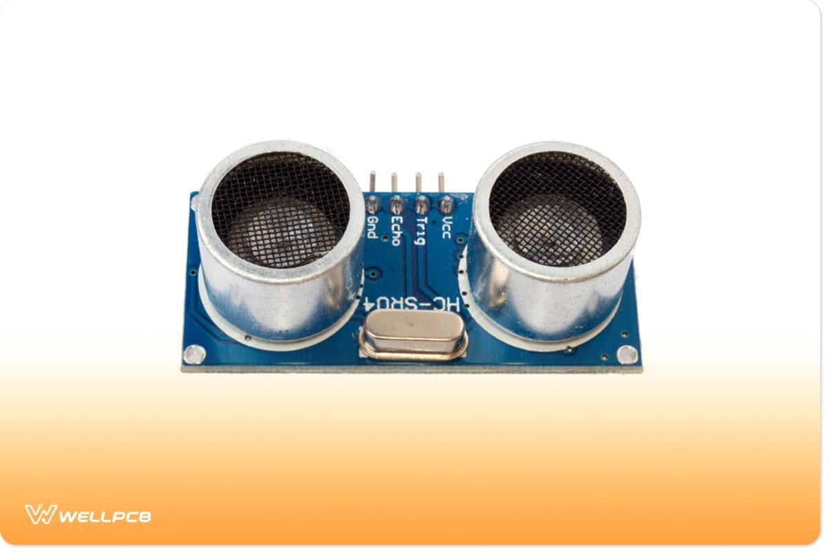
HC-SR04 Ultrasonic sensor
Before we begin with the tutorial, let’s cover a few things about the HC-SR04 Ultrasonic sensor. First, you’ll notice that the largest components on the ultrasonic sensor HC-SR04 are two identical cylinders. The left cylinder is what we know as the transmitter, while the other is the receiver. Consequently, you can tell which is which by the labels on the board (T = transmitter and R = receiver).
The transmitter sends ultrasonic waves while the receiver detects any waves that bounce back from an object. You’ll notice that the ultrasonic sensor HC-SR04 has four pins:
- Vcc pin: An input pin that powers the module (5V)
- GND pin: The grounding pin – you connect it to the ground on your microcontroller
- TRIG pin: The trigger pin – the transmitter pin (output pin that connects the transmitter component) – transmits a trigger pulse
- ECHO pin: An output pin for receiving signals (connects to the receiver component)
Nevertheless, this project aims to detect an object in front of the sensor and then display it. In this case, the project will display the results on the serial monitor. If you want to add some functionality or complexity to this project, you can add an RGB display.
Instructions
Connecting the Arduino board to HC-SR04 Sensor
First, let’s wire our circuit. Again, you’ll notice that the project is simple enough that you can use any cheap Arduino microcontroller.
1. Use one of your jumper wires to connect the Vcc pin from the HC-SR04 sensor to the 5V header on the Arduino Mega.
*Note: you can use the breadboard as a bridge or connect the HC-SR04 module directly to the Arduino
2. Next, connect the Gnd/GND on the ultrasonic sensor module to the ground (GND) header on the Arduino microcontroller
3. Connect the Trig (trigger) pin from the ultrasonic sensor module to header 10 on the Arduino microcontroller
4. Finally, connect the Echo pin to header 11 on the Arduino microcontroller
Once you’re done securing the above connections, you can start working on the code. You’ll need to connect your Arduino microcontroller to your PC through a cable. Again, you must ensure that you’ve installed the Arduino IDE and it’s functional on said computer.
Programming the Project
1. Connect the Arduino board to your computer.
2. Run the Arduino IDE.
3. Create a new sketch and name it sketch_nov08a.
4. Next, Include the NewPing.h library. (#Include <NewPing.h>)
*Note: The NewPing.h library contains an awesome slew of classes and functions that make coding for your ultrasonic component easy.
5. Next, instantiate a NewPing object and name it Sonar (NewPing sonar(10,11, 20)). Consequently, the Sonar constructor accepts three parameters:
- The trigger pin
- The echo pin
- The maximum distance in centimeters (the HC-SR04 sensor has a maximum distance of 4m)
6. Under the setup function, call the begin function from the Serial communication library and use 9600 as the argument – Serial. begin(9600)
7. Next, call the delay function with 60 milliseconds as the argument (delay(50))
8. Under the loop function, add a call to the print function from the Serial library with “The distance is:” as the argument (Serial. print(“The distance is:”)).
9. Again, add another call to the print function. But this time, add a nested call to the ping_cm function from the sonar object as an argument (Serial.print(sonar.ping_cm())).
10. Finally, add a delay of 1 second (delay(1000))
Once that’s done, run the code and port it to whichever port you have connected the cable to. The final Sketch should look like this:
If you’ve written and compiled the above code correctly, your console/serial monitor screen will look like this any time you place an object in front of the sensor:
If you’re interested in a more challenging project, why not visit our Arduino Proximity Sensor guide?
Conclusion
Working with ultrasonic or ultrasound is a great way to showcase how we can use echolocation in everyday technology. The above guide explored what an ultrasonic sensor is. Additionally, to help you understand the concept of ultrasonic detection, we also included a short tutorial that shows you how to use an ultrasonic module with an Arduino microcontroller. Nevertheless, we hope that you’ve enjoyed reading this guide. As always, thank you for reading.


