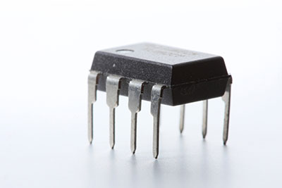
Circuits often need intuitive ways to switch power supply or protect other low voltage components. Hence a tiny circuit component known as the optocoupler is essential. It transmits electrical current between isolated circuits. It is also known as a photocoupler or an optical isolator. You can find the black four or six-pin in-home devices like your charger. Therefore, join us for a comprehensive look at the optocoupler and why it is such a valuable electronic component. Moreover, you can find the IC and accompanying details on our website.
Contents
- 1 1. What is an Optocoupler, and How Does it Work?
- 2 2. Optocoupler Inputs and Outputs
- 3 3. MOC3021 Datasheet: Features and Specifications of MOC3021
- 4 4.MOC3021 Pin Configuration
- 5 5. MOC3021 Datasheet: Where to use MOC3021 Phototransistor Optocoupler
- 6 6. MOC3021 Datasheet: How to use MOC3021
- 7 7. Applications of the MOC3021 Datasheet
- 8 8. MOC3021 Datasheet: The MOC3021 Equivalent
- 9 Conclusion
1. What is an Optocoupler, and How Does it Work?
Ideally, a typical transistor will only allow current flow once triggering happens at the base pin. However, if you carefully de-cap a discrete transistor, you can observe a tiny current flow through the emitter pin. Of course, that is after applying a voltage to the collector pin.
Thus, the current will flow even though the remaining parts are non-conductive materials such as glass or plastic.
The noticeable voltage is not due to AC application but photons on the transistor’s bare base. That means light induces conductivity in the semiconductor hence the existence of phototransistors.
Additionally, phototransistors are two-terminal transistors (without the base pin). They also come in clear packaging.
Comparatively, they look like diodes and use light as the base currency. They also work with photodiodes to detect a current shift in devices depending on incoming light intensity.
Consequently, a practical example is in proximity indication applications.
An optocoupler has two parts to transmit an electrical signal between two circuits. Besides, the two circuits are separate from the AC line to prevent electrical shock, a process known as isolation.
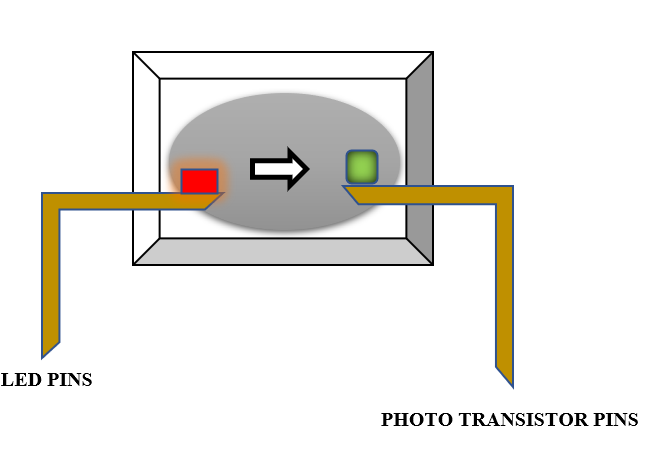
(Optocoupler working representation)
The two parts in the optical isolator are; an internal Light-emitting diode and a phototransistor that detects light. Thereupon switching happens depending on incoming light intensity. Therefore, an optocoupler combines a phototransistor, and an LED to control switching voltage.
That explains how it handles a switching element without physical contact.
A current input to the coupler lights the LED, thus producing infrared light proportional to the input voltage. Then, the transistor begins its normal functioning process on detection of the morning.
One can connect an external resistor to the ground for faster-switching speed.
2. Optocoupler Inputs and Outputs
Generally, optocouplers consist of a diode at the input and a switching element at the output.
The diode is light-emitting; however, you cannot see the light because of the optocoupler’s box. Also, the light from the diode is infrared, thus not easy to see.
The light diode runs on the same voltage amplitude as a typical LED.
The output end may have an NPN transistor, a TRIAC, a Silicon-controlled rectifier, or even a complete logic-capable output.
Since the base current at the output is driven by light energy, it is usually low.
The low base output voltage also slows down the rise and fall time. Though, one can use a logic output and an optocoupler of matching speeds to remedy this. However, doing it will require a different output terminal voltage.
(Pinout diagram of an optocoupler)
The primary advantage of an optocoupler output is that it can conduct voltage isolation from the input voltage. Thus, it acts as a floating switch, although not one of quality.
For instance, you can use a transistor at the low end and add a pull-up. Every time the diode is on, it activates the transistor to pull the collector low.
Also, a transistor at the high end plus a resistor between the output ground and emitter would pull the emitter high at the output.
However, regular optocouplers have a limiting base drive that results in high saturation up to a whole volt. Optocouplers’ slow speeds and isolation voltage characteristics are efficient power supply feedback loops.
Additionally, the current rating does not allow it to supply power as a generator does.
On the flip side, an optocoupler can efficiently transfer signals between circuits without the help of separate drivers.
3. MOC3021 Datasheet: Features and Specifications of MOC3021
A version of the optocoupler zero-crossing TRIAC exists, the MOC3021.
Its infrared emitting diodes contain gallium arsenide and a bilateral silicon switch.
Its other features are;
- When the peak AC voltage is at 60Hz for 1second, it has an isolation surge voltage of 7500Vac (pk).
- An ambient temperature (TA) range of -40 to + 85 °C.
- A storage temperature (T stg) range of -40 to +150 °C
- Total power dissipation (PD) with the TA at 25 °C is 330mW. Duration above 25 °C is 4.4m/W°C
- Junction temperature range (TJ) OF -40 to 100 °C.
- Soldering temperature (TL) for 10s is 260°C
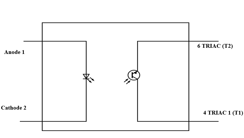
4.MOC3021 Pin Configuration
| PIN | pin name | description |
| 1 | Anode (A) | IR LED anode pin. Connects to the logic input |
| 2 | Cathode (C) | IR LED cathode pin |
| 4 | TRIAC Main Terminal 1 | TRIAC end inside the IC |
| 6 | TRIAC Main Terminal 2 | Another TRIAC end inside IC |
Pins 3 and 5 have no connection.

5. MOC3021 Datasheet: Where to use MOC3021 Phototransistor Optocoupler
The MOC3021 is a choice for an optocoupler that controls AC applications via a direct current. But, operating temperatures in high loads impact the circuit performance. Fortunately, the MOC3021 can withstand high temperatures, thus maintaining the optocoupler’s life quality.
Since a TRIAC drives its output, it can cause a 100V load. That, plus the fact that the TRIAC operates in both directions, makes it easy to control the AC loads.
The zero-crossing capabilities allow it to prevent damage due to direct peak voltages. It does this by initiating AC conduction. However, that is after the AC wave hits 0V when it switches on for the first time only. The decent rise and fall times also allow control of the output voltage.
Therefore, the MOC3021 is ideal for controlling larger AC voltage loads in digital controllers like the MCU/MPU.
Since it is possible to control the output, it is also possible to maintain an AC motor’s light/speed intensity.
Here is a video of a project involving the optocoupler.
6. MOC3021 Datasheet: How to use MOC3021
The MOC3021’s current limiting does not allow it to drive voltage loads directly. Like a TRIAC, it requires another power switch that provides enough current to move the loads.
Notably, in this setting, the optocoupler acts as a controller.
Also, the MOC3021 switches loads by turning the LED on or off. Alternatively, PWM signals can also help change the LED hence the TRIAC. Once the TRIAC is on, it can control the load’s brightness and speed.
The photocoupler’s switching speed is an essential factor when switching AC loads. The speed depends on the voltage amplitude and the operating ambient temperature of the photocoupler.

(MOC3021 interfacing diagram)
7. Applications of the MOC3021 Datasheet
The general use of the MOC3021 is to control an AC appliance. Hence, it is helpful in;
- AC/DC Power control
- AC motor speed control
- AC Light dimmers
- Strobe lights
- Using MCU/MPU to control AC loads
- Noise coupling circuits

(Siren strobe lights)
8. MOC3021 Datasheet: The MOC3021 Equivalent
Alternatively, one can use the following optocouplers as replacements of the MOC3021.
- FOD3180 (High-Speed MOSFET)
- MCT2E (non-Zero transistor)
- MOC3041 (Non-Zero Cross TRIAC)
Conclusion
An optocoupler is an exciting gadget, especially its implementation into various devices. Hopefully, the above illustrations enhance your understanding of the gadget. Should you have inquiries or need assistance, reach out through our website.


