
Contents
- 1 CCAElectronicss General Concept
- 2 Procedure
- 3 The Four Components Of A CCA?
- 4 What Is The Difference Between A PCB And A CCA?
- 5 The Three Circuit Card Assembly Types
- 6 Methods To Create CCAs
- 7 The Best Mounting for CCA
- 8 Consider These Factors Before Choosing a Circuit Card Assembly Manufacturer
- 9 Everyday Applications of CCA
- 10 Advantages and Disadvantages of CCA
- 11 Basic Electronic Components In-Circuit Card Assembly
- 12 Can You Repair Circuit Cards?
- 13 Conclusion
CCAElectronicss General Concept
Metal is used to attach the components of electricity to the board so that it can conduct electricity.
In most cases, the copper used is etched on the inside of the board, which is usually between the plastic layers or maybe on the board’s surface.
This is meant to ensure that electricity goes only to the areas where it is required.
The metal etched on this board allows electricity to travel from one component to the other within the electrical circuit.
The boards can have several parts connected and still work together.
In most cases, circuit cards are produced more significantly for a given job, such as running a computer, television, or mobile phone.
Circuit cards are the ones that are very thin with suitable material that can flex.
Flexible CCAs are used in making cables that are tiny and very lightweight circuits.
Procedure
The procedure for making CCA electronics products is as follows:
1. Get a copper-coated film.
2. Use a solid-ink printer when printing directly on the copper film.
3. Print on the parallax. Draw a design for either of the graphics programs and then use a feed tray that is manual to print on the parallax sheet.
The published areas will be protected by wax and will end up with copper traces on the layout. When printing, one should use the high resolution or the photo mode.
The high-resolution method is slow in printing, but it promotes better adhesion from wax to copper.
4. Etch it. In CCA manufacturing, the sheet printed should be put in ferric chloride for about five minutes.
The etching will depend on the thickness of the copper, temperature, and other conditions. The copper areas should melt, and a polyimide film should appear.
If you plan to cut it into small circuits, then solder. 5. Populate the card. It can now be taped to metal or a regular fiberglass circuit board to hold it steadily.
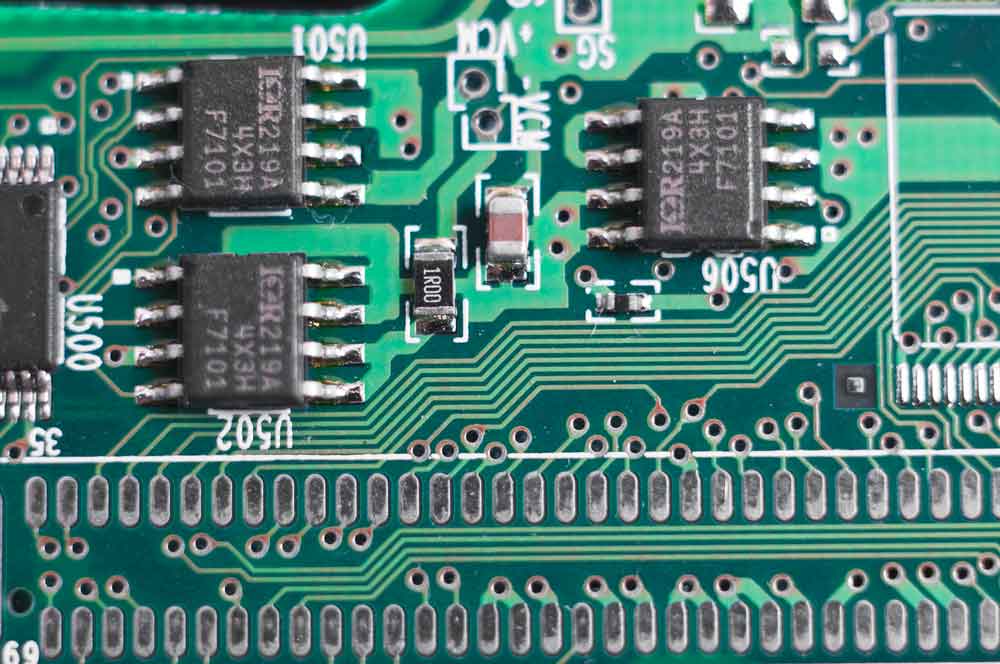
The Four Components Of A CCA?
Of all the different designs available in CCA, the basic components are similar.
There are four components in the circuit card assembly manufacturing process.
Substrate
The substrate is the fiberglass conductive material that holds all the electrical components together.
Manufacturers use a copper plus heat laminate to make it conductive.
Usually, the substrate has multiple copper layers, but it might be a single layer.
Whether it’s a metal core, ridged, or flexible substrate, you will find components such as
- Slow energy-release capacitors
- Voltage-control resistors
- Chokes that smooth out electrical current
- Transistors
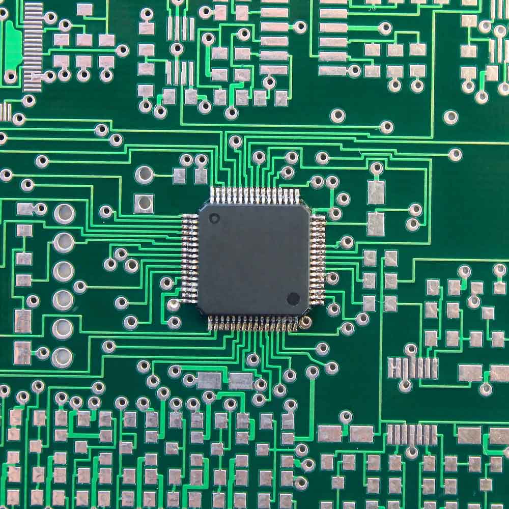
Copper Foil
As mentioned above, the CCA wouldn’t function without copper, which lends its superb electrical conductivity to the board.
It forms the bridge between the substrate and tracks or traces.
The manufacturer follows your design to determine whether they will use single–, double–, or multiple-layer copper boards.
Solder Mask
If you look at a circuit board, you will notice a yellow or green tint. The tint is a polymer resembling a lacquer.
The solder mask is a protective coating on the copper layer. It has two primary functions.
- It prevents metal-to-copper contact that would short the board.
- It prevents oxidation damage.
- Also, there won’t be solder bridges between solder pads.
Silkscreen
The silkscreen has numbers and letters that tell the engineers where various LEDs and pins go. This topmost board also helps to identify test points.
What Is The Difference Between A PCB And A CCA?
Circuit card assembly vs PCB has more similarities than differences. In a nutshell, they’re interchangeable terms only separated by some technical aspects.
There’s a difference between PCB vs.s CCA and PWB vs.s PCB. A Printed Wiring Board is an on-printed circuit board without components on which manufacturers lay components and then wire them.
A PWB’s dielectric epoxy glass substrate provides a platform for point-to-point wire connections.
| PCB | CCA |
| PCB manufacturers can complete the process in one go. | Circuit card assembly manufacturers make CCAs in several stages. |
| PCB manufacturing focuses on building the board, led by engineers. | The circuit card assembly manufacturing process leans more toward design by technicians. |
| PCBs are single boards with multiple components that complete a circuit. | CCAs can have multiple PCBs |
| You can connect several crucial electronic components in a PCB. | CCAs connect electronic parts. |
The Three Circuit Card Assembly Types
- Surface Mount Technology Assembly involves fastening metal tab segments to the PCB. High-density PCBs usually have these segments on both sides of the board.
SMT assembly is an automated process popular for churning out circuit boards in large quantities.
- Box-build circuit Card Assembly involves designing, manufacturing, and installing electrical parts into printed circuit sheets. The complete box-build CCA is a functioning system in an enclosure with cables, PCBAs, electrical systems, and optional pneumatic components.
- Through-hole circuitt Card Assembly is reserved for applications with huge transformers and electrolytic capacitors. Here, circuit card assembly manufacturers place leads from electrical components into holes in the board and then solder them to pads on the boards’backsk.
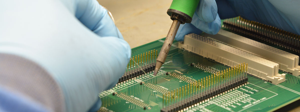
Methods To Create CCAs
Manufacturers use three methods to create CCAs.
When using manual methods, they place components on electronic devices and solder them to complete permanent connections.
Since it takes too much time, manual CCA creation is reserved for small CCA batches.
Manufacturers opt for semi-automated methods to speed up the circuit card assembly manufacturing process, maintain a lean budget, and improve quality standards.
Machines place the components and check positioning before placing them on boards.
The last method, automated CCA assembly, uses fully automated processes optimized for speed and efficiency.
Machines place the components on the board, paying extreme attention to precision and detail.

The Best Mounting for CCA
The best mounting for CCA ensures the least time consumption and maximum precision.
Thru-Hole Mounting
In this technique, you place each component on the board instead of under the board’s surface for maximum aesthetic appeal and functionality balance.
Ball Grid Array Mounting
This mounting technique involves manually placing components on the PCB with bonding wire. After verifying they’re in the correct position, you solder the parts.
T and R Mounting
Hold the PCB using a fixture and solder components in their places.
Surface Mount Technology Mounting
This mounting approach uses laser drilling to group electronic components on a circuit board. It uses minimal solder to maintain low thermal resistance.
SMT mounting brings out more compact electronic devices.
Each mounting technique serves a different purpose for a manufacturer. Therefore, you can use multiple techniques (mixed-technology mounting) to get the best results from each technique.
Consider These Factors Before Choosing a Circuit Card Assembly Manufacturer
Whether you want PCBs or CCAs, evaluate these four make-or-break factors while picking manufacturers.
Lead time: Ensure your manufacturer can deliver precise-to-detail finished products within a specified deadline. Otherwise, you might have a production backlog.
Quality of material: CCAs are central to consumer electronics and other vital systems. Ensure the manufacturer uses high-grade material that will not cause failure and potential damage.
Also, ensure the material passes QC standards such as Registration, Evaluation and Authorization of Chemicals(REACH), Restriction of Hazardous Substances(ROHS), and conflict materials.
Speed and efficiency: Speed and efficiency might call for the use of one assembly method over another.
For example, you may want to choose a manufacturer using SMT over BGA. Ensure they have strict QA checks to guarantee accurate drilling, component placement and board tests.
Cost: Bulk production can escalate costs. Therefore, shop around for manufacturers offering a balance of cost, high quality, and efficiency.
Customer Service: Maintain a friendly yet professional customer-client relationship with your manufacturer. That way, they can address your speed, quality, cost, and time concerns.
Everyday Applications of CCA
- Low-power home electronic goods such as TVs, sound systems, and other consumer electronics use CCAs.
- You’ll find CCAs in medical devices such as MRIs, ultra-sound equipment, and CT scans.
- CCAs feature in the aerospace industry in communication machines, satellites and air travel vehicles.
- The industrial electronics field uses CCA for control systems and emergency service equipment.
- If you open up a unit with microcontrollers and storage systems, you will likely find CCAs.
Advantages and Disadvantages of CCA
| CCA Pros | CCA Disadvantages |
| Lackluster monitoring standards that cause a drop in quality can be harmful, especially in consumer goods and highly sensitive applications. | Some aspects of Circuit card assembly can be expensive, especially for commercial units. |
| Electronics have become more affordable. | Lacklustre monitoring standards that cause a drop in quality can be harmful, especially in consumer goods and highly sensitive applications. |
| Smaller electronics allow better space management. | Computer-designed CCAs can be difficult to repair. |
| Strict assembly guidelines mean better safety standards and higher quality final products. | Mass production is still a challenge when using CCA. |
| Concept design and manufacturing of CCA leads to more innovative takes on everyday electronics. |
Basic Electronic Components In-Circuit Card Assembly
Resistors
Resistors in CCA oppose current flow. They act as voltage regulators that prevent the system from being overloaded in case of excess electrical supply.
Inductors
Like resistors, inductors are passive components. They store electrical energy and release it to the board with a low supply. They block alternating current while allowing direct current.
Capacitors
These are another passive component in CCAs that regulate energy. They act like inductors, storing energy to release when needed. However, unlike inductors, they allow alternating current and block direct current.
Transistors
You can find Bipolar Junction Transistors or Field Effect Transistors in CCA. They regulate current in electrical systems either by amplifying or switching current.
Diodes
Diodes in CCA act as current rectifiers. Sometimes, AC is converted to DC. The diode rectifies this action and makes the current flow in one direction.
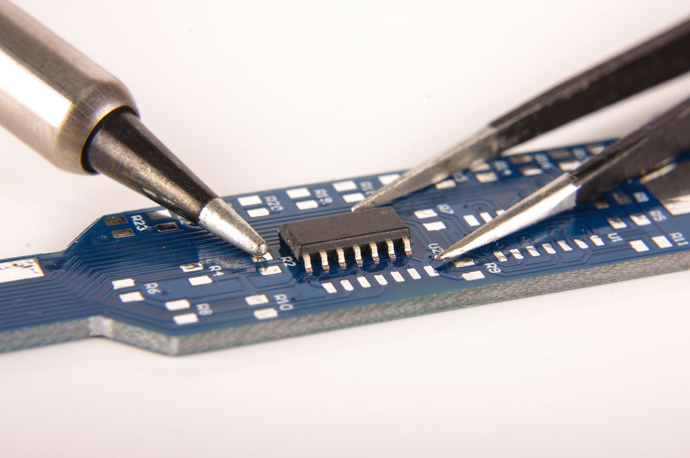
Can You Repair Circuit Cards?
As much as circuit card repair is possible, it’s not easy. They are extremely complex structures that can be rendered useless by the slightest damage in sensitive sections.
However, a skilled engineer can pinpoint the cause of circuit card damage and recommend repair measures.
Causes such as trace damage, terrible design, individual component damage, poor handling, and power-related damage could require circuit card repair.
But, you can avoid constant repair by trusting the right manufacturer, limiting humidity, and monitoring the circuit card’s deterioration rate.
Conclusion
The use of CCA electronics has become an essential part of the day to day operations.
It has some differences with PCB assembly, but both markets relate to each other.


