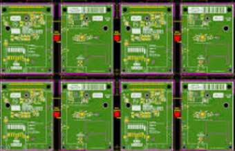
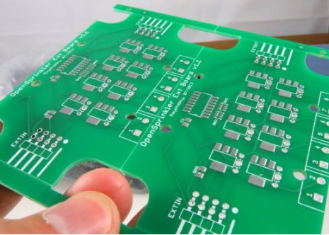
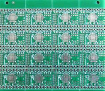
Panelization PCB is one of the methods that help to design an array of PCBs into a single piece to make working on it more accessible. Unfortunately, there are no hard and fast rules that must be followed during the panelization process. Factors such as the thickness of the PCB, the construction, and the design play an essential role in determining the guidelines to be followed during the process. Panelization is critical, especially in cases where the PCB needs to fit in a given space. It will, therefore, help you come up with an array of designs that serve the need.
Contents
1.Panelization PCB—Panelization PCB Methods
The choice of panelization method to use is determined by the design of your board and the number of components that are used. Also, it is essential to consider the features that hang on the edge of the board before choosing a method of panelization which ensures that the right PCB array strength is achieved.
To improve the strength of the panel, solid tabs may be used. In such cases, laser- cutting machine depaneling router may be chosen. If you decide to use a paneling router, you must be prepared to hold the fixtures tightly since it vibrates and produces dust and noise. On the other hand, using the laser-cutting machine is capital intensive and may be limited to just about 1 mm. Notice that solid tabs between boards should be removed using appropriate tools. Among the tools you may opt to use include the hook-shaped blade tool.
2.Panelization PCB—Depanelization
Refers to the cutting of tabs to individual PCB boards. It is a manufacturing step that helps in cutting panels into multi-boards. Aims at increasing the throughput of the printed circuit board. It allows for designing PCBs to consist of smaller PCBs that can be aligned and inserted into an array to form a final product.

3.V-Groove and Perforated Methods
V-grooves and perforated tabs are the best depanelization methods you can use. In the case of the V-Groove panelization method, it requires that you cut 1/3 of the board at the top and another 1/3 at the bottom. The cutting may be done at an angle of 45 or 30 degrees. One may also need a cutting machine and other tools to do the paneling effectively.
Using V- groove method may cause several problems. Still, it is the preferred method because it does not allow components to hang over an edge, and surface stress is significantly reduced. It is also economical because the machines used are inexpensive and require little maintenance and adjustment.
Most of such machines are portable and can easily be moved around when the need arises. Unfortunately, V-groove methods come with many restrictions, especially where the components are hanging on the edge of your board. Also, it cannot be used to cut straight lines via the PCB array.
4.Breakaway-Tab Panelization Method
The method is suitable when V-grooves cannot be used. It keeps surface-mounted parts away from perforation holes and helps to stop splintering and damaging the tabs. The technique employs a three or five-hole pattern and charges which are placed under overhanging parts.
In some cases, you may need to use removable knock-outs to help fill holes to prevent the solder from running into the board. In some cases, a five-hole breakout tab may be placed on any of the sides.