
Switching the regular lighting circuit on and off is a simple undertaking. But how about a night light circuit that switches on after dark? Our article explicitly covers creating an automatic night light circuit using simple electronic components.
Contents
9V automatic night light circuit
Circuit Diagram

Key Components

Circuit Explanation
The photoresistor in the circuit plus the 100 kΩ resistors create a voltage divider of the emergency lights circuit. Hence, the photoresistor has relatively low resistance when there’s a lot of ambient light/normal room light. Therefore, the transistor remains off, and the LED receives no sunlight.
Conversely, the photoresistor’s resistance is high when ambient light levels are low. Thus, there’s a high output voltage at the transistor. In turn, this will put on the transistor and, by extension, the LED.
Notably, the voltage divider’s output is 0.5V at a low light level and 4.5V in the dark.
Automatic night light circuit using 2N3904
Circuit Diagram
Set up the course as shown in the diagram below.
Components Needed

Circuit Explanation
Notably, standard simple circuits with current-driven components feature NPN transistors. Nonetheless, using NPN-type transistors necessitates a positive current in the transistor’s base lead.
Conversely, for a PNP transistor, turning it on requires an adverse current or a base lead ground level to function. Hence this informs our decision to use a PNP rather than an NPN, as shown on the circuit diagram.
The photocell is a light-dependent resistor. Hence more exposure to light prompts low resistance on its leads. Again, the high resistance resistor and the photocell create a voltage divider which is handy in controlling the supply voltage to the LED.
Automatic night light circuit of LM324 Amplifier
Circuit Diagram

Parts List

Circuit Explanation
The photoresistor is significant in sensing the incident light intensity and varying its resistance accordingly. Hence, this component activates the nightlight to go on automatically once ambient light dims.
Again, a voltage divider is necessary for this circuit, which functions via interfacing with a resistive transducer. In our case, the photoresistor takes the role of the transducer. In addition, we have two resistors in series to operate as the voltage divider.
The equation below gives the output voltage at the voltage divider:
V (Out) = V (In) x Rw ÷ (Rw + Rv)
Thus, as the above equation tells, the voltage divider’s output is directly proportional to the Rv and Rw values. Also, as Rw increases, V (in) has a closer semblance to V (out). Hence, it would help if you had the photoresistor as the Rw resistor.
Lastly, the LM324 acts as the comparator in the circuit. It’s essential to compare the inverting input voltage to the non-inverting input voltage. If the latter is greater than the former, the comparator’s output turns on the LED and vice versa.

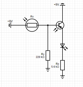
Automatic night light circuit with one LED
Circuit Diagram

Key Parts

Circuit Explanation
In earlier circuits, we used a photoresistor, but we’re using a phototransistor in this case. The latter is better in response. Thus, the LED will go on immediately rather than delayed, as in the case of a photoresistor.
When there’s enough ambient light, the phototransistor enters conductive mode. Simultaneously, its emitter voltage rises. Next, the base level voltage of the PNP transistor prompts it to go to the cut-off region. Thus, the LED will remain off.
Conversely, at night, the phototransistor is in the cut-off state. A decrease in the emitter voltage accompanies this. Hence, the transistor connects to the ground via the resistor, thus inducing conduction. In turn, this switches on the LED.
Automatic Day Night on off Switch Night Circuits
In another article, we’ve explicitly elaborated on this kind of circuit. Click this link for more insights into this topic.
Conclusion
Above are some of the critical variations of a night light circuit. For more on this, feel free to contact us anytime, and we’ll respond to your query immediately.


