NiMH batteries have higher energy densities, have 30 percent more capacity than NiCad batteries, and are environmentally friendly. However, most people don’t know how to recharge them or the working of the NiMH battery charger circuit.
Luckily, here at WellPCB, we’ve got qualified professionals willing to help. But first, read on.
Contents
Features
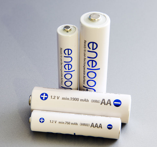
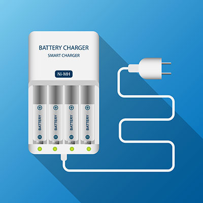
Fig 1: NiMH rechargeable battery pack cells
Source: Wikipedia
The NiMH charger circuit has many features, but here’s a brief look at the main ones.
- First, it has a complete fast charger controller for 1-, 2-, 3-, or 4-series cell NiMH batteries.
- Second, it has an input supply range from 4.5V to 10V.
- Also, the circuit automatically detects the battery.
- Fourth, the circuit doesn’t need a sense resistor or blocking diode.
- Fifth, It is a fast charge current programmable over 2A using an external sense resistor.
- Additionally, it has a negligible battery drain of less than 1uA in sleep mode.
- Seventh, the circuit doesn’t require firmware or a microcontroller to run.
- The circuit supports manual shutdown when not using a smart battery.
- Ninth, it has a precharge for heavily discharged batteries.
- Furthermore, it has an automatic recharge feature to keep the rechargeable batteries charged.
- Finally, It is available in TSSOP and 16-lead DFN packages.
How Does the NiMH Battery Charger Circuit Work?
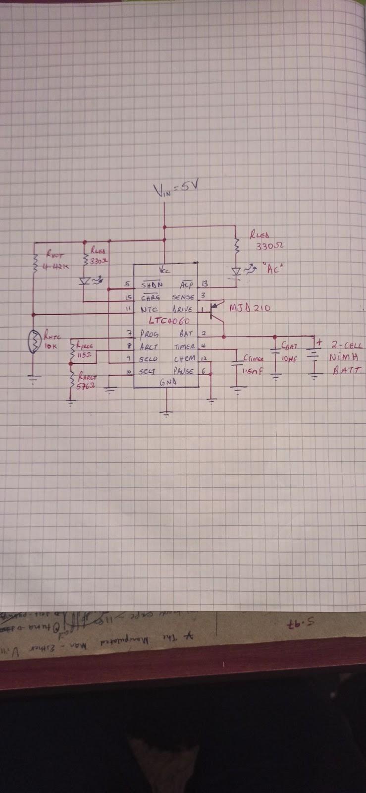
Fig 2: A simple NiMH circuit diagram
The NiMH battery circuit is easy to work with and requires a single NiMH battery charger IC to protect the battery while it’s charging. Consequently, it remains in a conducive environment while simultaneously charging quickly.
Now, let’s look at how the NiMH battery circuit works.
When the circuit is not powered, the NiMH charger IC enters sleep mode, and the charging battery is disconnected. Additionally, the disconnection and sleep mode happens when the NiMH charging voltage exceeds the IC’s threshold (overcharged).
The IC enters sleep mode when the supply Vcc exceeds the under voltage lockout (ULVO) fixed limit. The result is that it then disconnects the battery from charging.
And it’s the potential difference levels across the connected battery cells that determine the ULVO limits of the battery. Consequently, these limits are flexible and determined by the number of connected cells.
However, you must initially program the IC with the number of battery cells connected using suitable component/ device settings. These components determine the charging rate and include a programming resistor connected to the IC’s PROG pin. With the current setup (Fig. 2), an inbuilt amp sets a 1.5V virtual reference across the PROG pin.
As a result, the programming current passes through an inbuilt N-channel FET and towards the current divider. The current divider creates a potential difference across the resistor resulting in a fast charge for the battery. Also, it’s responsible for creating a constant current level in the battery.

How To Build This Project?
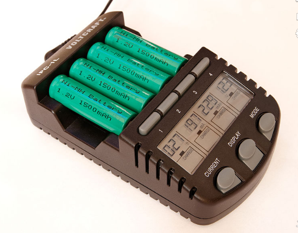
Fig 3: A simple NiMH battery charger
Source: Wikipedia
Components Required
- 0-12V AC step-down transformer
- 1N4007 X 4 or bridge rectifier module
- TIP125 PNP transistor
- Resistors: 47Ω, 10Ω, 2KΩ, 1KΩ
- 2 LED lights/ resistors
- Two 330uF capacitors
- 9V NiMH battery
How to Connect
You need to charge NiMH batteries slowly and at a low current. For your information, overcharging or overflowing the battery causes it to heat up. A step-down transformer transforms 230V AC power into 12V AC power.
The bridge rectifier modules turn AC power into DC power, whereas capacitor C1 handles filtering duties. Furthermore, Darlington Transistor TIP125 is connected to the positive supply line for current regulation and guarding the battery against overcharging. LED1 indicates the presence of the battery at the output and supply flow.
It’s linked between the positive supply and TIP125’s base terminal, then resistor R1. LED2 indicates the output DC supply when you couple it across the output with R4 Resistor.
How To Charge a NiMH Battery
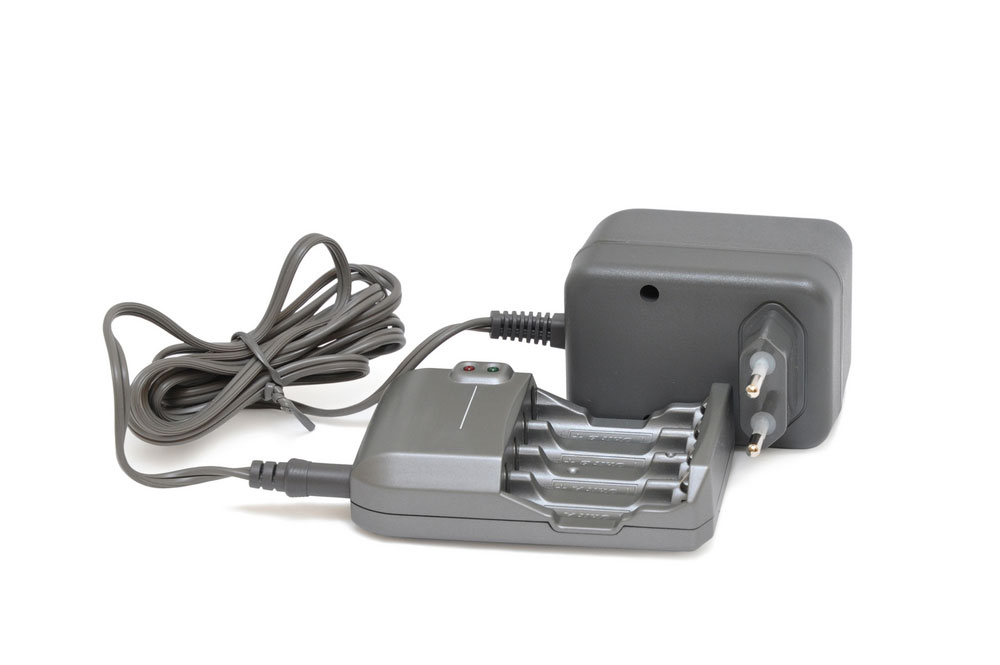
Fig 4: Panasonic Eneloop Pro rechargeable nickel metal hydride (NiMH) batteries
Charging NiMH batteries is challenging as they lack the “float charge” voltages synonymous with lithium-ion batteries. Consequently, you must consider overcharge, charging rates, trickle charging, and charging manners to prolong battery life.
The NiMH batteries have similar properties to the NiCad batteries but suffer a reduced capacity if overcharged. Additionally, you must charge them through slow charging and a constant current charging method.
Here is how to charge a NiMH battery.
Timer Charging
Timer charging is the easiest NiMH battery charging method.
Here an inbuilt electronic timer determines the end of charge by assuming that the battery was 100 percent discharged beforehand. However, this method is flawed if a battery has lost a percentage of its capacity resulting in an overcharge.
Thermal Detection
Using temperature rise to determine the end of charge is flawed thanks to difficulties in telling the accurate battery temperature.
Negative Delta Voltage Detection (NDV)
The NDV method detects a charge voltage drop that appears once the cell gets a full charge. However, you must include a noise filtering circuit in your charger to detect the tiny voltage drops in NiMH batteries.
Consequently, many modern NiMH chargers employ the three methods listed above to detect the end of charge. These types of battery chargers use NDV and temperature rise detection. They also use a timer in case they bypass the former two methods.
Conclusion
NiMH batteries are robust batteries that often fail due to overcharging. Therefore, it’s essential that you correctly charge them with a suitable charger and at room temperature. If you adhere to those guidelines, you can safely use them for extended durations.
Finally, feel free to contact us if you have any gray areas that need clarification or assistance with your project.


