Bluetooth Low Energy (BLE boards) is a wireless network technology manufactured for fitness, security, and healthcare applications. Despite being independent of a standard Bluetooth, it can coexist with LE and BR/EDR (Bluetooth Basic rate/enhanced data rate). A BLE device has two forms, modules and chip form. One BLE integrated circuit chip example is nrf51822 Arduino falling under the NRF51 series SoC (system on a chip). Another class from nrfGo studio with personalized advertisements on are NRF52 board and nrf5 board.
Contents
What is nrf51822 Arduino?
NRF51822 is a wireless 2.4GHz RF SoC/Multi-protocol BLE (Bluetooth Low Energy) module built for ultra-low-power (ULP) wireless applications.
Its little breakout board comes in a tin package and should have CE, TELEC, and FCC certifications. Furthermore, you’ll also find a chip antenna and supporting circuitry to aid in low power consumption and peripheral role.
Features and Specifications
The features and specifications of nrf51822 are as follows;
- First, it has a power supply voltage range of 2.0V to 3.6V.
- Its operating temperature range lies between -40°C to +85°C.
- Then, nrf51822 has an onboard antenna and an ARM® Cortex™-M0 32-bit processor.
- Thirdly, it can digitally interface with UART, I2C, and SPI and has a programmable peripheral interconnect (PPI). Further, its programmable output power ranges from -20 to +4 dBm TX power.
- Also, it has pinout compatibility with the NRF51xxx series while fully being compatible with the NRF24L series.
- Fifthly, the Nordic semiconductor nr51822 global management is globally separate.
- It also has encryption of 128-bit AES HW with 32kB RAM and 256kB flash.
- The 10-bit ADC chip has an independent protocol stack and application development.
- In addition, it has a communication distance (i.e., open outdoor at a data rate of 1M) of 30m.
- Its frequency range of 2.4GHz is of a multiprotocol RF transceiver type.
- All the I/O pins have an expansion pin header except P0.27 and P0.26. Besides, its pin-header pitch is 2.0mm and has a spacing of 18.00mm between its right and left sides.
- Lastly, its PCB dimension is 20.8mm × 17.0mm and weighs 0.9g.
Application
The applications of nrf51822 Arduino include;
- Industry control,
- Wearable devices,
- Lifestyle and healthcare sensors,
- Proximity and security alert tags,
- Toys and electronic games,
- RFID labels,
- CE remote control for STB, media systems, and TV,
(TV remote control)
- Beacons,
- Bluetooth intelligent application,
- Data acquisition system,
- Mobile phone accessories, and

(mobile phone accessories)
- Smart home appliances.

nrf51822 Arduino Project introduction
You can try out the power BLE project below using an NRF51822 Arduino IDE.
Parts list
They include;
- A Personal Computer with either of the Operating Systems below;
- Linux,
- Windows 8. x, 7, or 10,
- Mac OSX 10.9x, 10.10x, or 10.11.4.
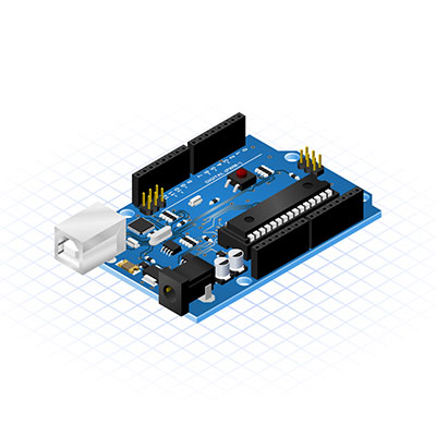
- Development boards such as RBL nrf51822 or nrf52 module,
- A support package of the development board with a 1.0.6 add-on feature
- Arduino IDE version 1.6.9.
Steps
- Install Arduino IDE into your PC after retrieving it from the website.
- To start the Arduino IDE operation, click on the preference.
- Use the following procedure: Tools -> Board Menu –> Board manager to help install the nrf51822 board’s add-on.
- Next, if you’re using a Windows PC, get the USB serial/CDC driver, then finish its installation. The purpose is to enable you to upload sketches in your Arduino IDE while using the serial port.
- If you’re using Linux, include udev rules, then afterward, restart your system.
- Further, correct the upload challenge on your 64-bit Linux systems.
Bootloader
- Here, you’ll find a bootloader. Hex firmware is located in the bootloader folder for your development board. It helps you load an Arduino sketch while utilizing an Arduino IDE.
- Connect the nrf51822 board to the PC via a compact USB port to load the bootloader. Consequently, the action will signal a drive. Then, you’ll drag the firmware to your CDC drive.
Note;
You can also follow through with OTA sessions for more instructions since the bootloader possesses an OTA feature.
Alternatively, you can skip the bootloader step altogether.
Test
- Start by selecting the development board (nrf51822) or BLE nano board from the Arduino IDE menu.
- Then, select your serial port via; Menu –> Tools –> Ports –> [Your serial port board name]. The port alongside a USB interface dongle helps in getting a printout.
- Next, loading the blink example helps test the board and see if it’s working.
- Finally, load the Arduino sketch to the development board from the upload icon, and voila!
One of the Bluetooth Low energy illustrations you can attempt include;
- BLE_Beacon,
- BLE_HRM (Heart Rate Monitor), or
- BLEController.
Step – Menu –> File –> BLE_Examples.
NRF51822 module advantages
You’re probably wondering why you should settle for the NRF51822 module. Below are the reasons.
Easy in application
Nrf51822 has an inbuilt antenna that makes development more straightforward. Thus, you can apply the module without worrying about radio design issues like soldering fine pitch and specific impedance matching.
High performance and cost-effectiveness
Its built-in PCB antenna minimizes material cost while offering quality performance.
Ease of connection to iOS or Android
Nrf51822 is a BLE (Bluetooth Low-Energy) module with low power consumption.
Presence of a low power wireless technology
A micro nrf51822, by default, functions as Bluetooth Low Energy to any UART device. Therefore, connecting the module to an Android or iOS via the nRF UART app becomes easy.
Conclusion
We have come to the end of our discussion on Bluetooth Low Energy technology that involves the nrf51822 chip. If you have questions or need clarifications for your analytical purposes, please contact us.


