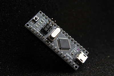
If you’re looking for a well-known microcontroller that will nail your projects quickly, you can consider the PIC16F877A. Asides from that, the device is pretty convenient to use and a breeze to code or program the controller.
Plus, the device has a FLASH memory technology that allows you to write-erase multiple times. So, do you want to learn more about this device before using it on your PIC microcontroller projects or digital electronics circuit?
Well, the good news is;
We created this article to boost your knowledge of the PIC16F877A by explaining the basics, its applications, how to program it, and more.
Let’s begin!
Contents
- 1 PIC16F877A Microcontroller: Introduction and Features
- 2 PIC16F877A Microcontroller: The Pinout Configuration
- 3 PIC16F877A Serial Port
- 4 Compiler for PIC16F877A Microcontroller
- 5 Circuit Diagram for Flashing LED with PIC16F877A
- 6 How Do You Select Your PIC Microcontroller?
- 7 How Do You Program the PIC Microcontroller?
- 8 Applications of the PIC16F877A
- 9 Final Words
PIC16F877A Microcontroller: Introduction and Features
The PIC16F877A is an easy-to-program and robust CMOS 8-bit microcontroller compatible with different devices like;
- PIC16C7X
- PIC16C5X
- PIC162CXXX
Plus, the device packs a lot of power in its 40 or 44-pin package.
Also, the microcontroller has an EEPROM that allows you to permanently store essential data like receiver frequencies, transmitter codes, etc.
Interestingly, the PIC16F877A is cost-effective and easy to handle. And thanks to its flexibility, the device works in places you have never used a microcontroller before.
Features of the PIC16F877A
- The device runs up to 20MHz frequency.
- It doesn’t come with an internal oscillator.
- It can source a maximum current of about 100mA. Hence, the PIC16F877A’s GPIO pin current limit is 10mA.
- The PIC16F877A has a smaller 35 instructions set.
- The microcontroller is available in four IC packaging: 44-pin QFN, 40-pin PDIP, 44-pin TQFP, and 44-pin PLCC.
The PIC16F877A has an operating voltage range of 4.2 to 5.5V. So, if you offer over 5.5V, it may damage the microcontroller permanently.
Other features of the PIC16F877A are in the table below:
| Data EEPROM | 256 bytes |
| PROGRAM Memory Type | Flash |
| Communication Peripherals | MSSP (SPI/12C), UART (1), 12C (1), SPI (1) |
| Timer Module | 8-bit (2), 16-bit (1) |
| RAM Bytes | 368 |
| CPU | 8-bit PIC |
| Number of I/O Pins | 33 |
| CPU Speed (MIPS) | 5 MIPS |
| DAC Module | None |
| Number of Pins | 40 |
| Program Memory (KB) | 14KB |
| ADC Module | 8ch, 10-bit |
| Comparators | 2 |
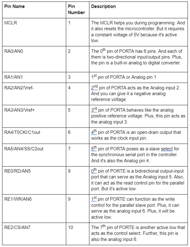
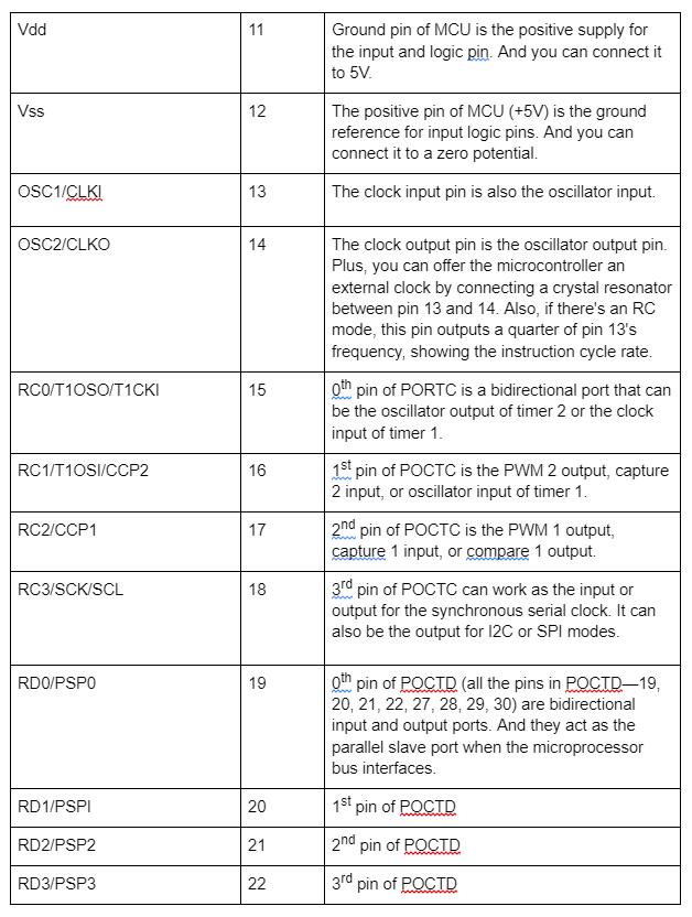
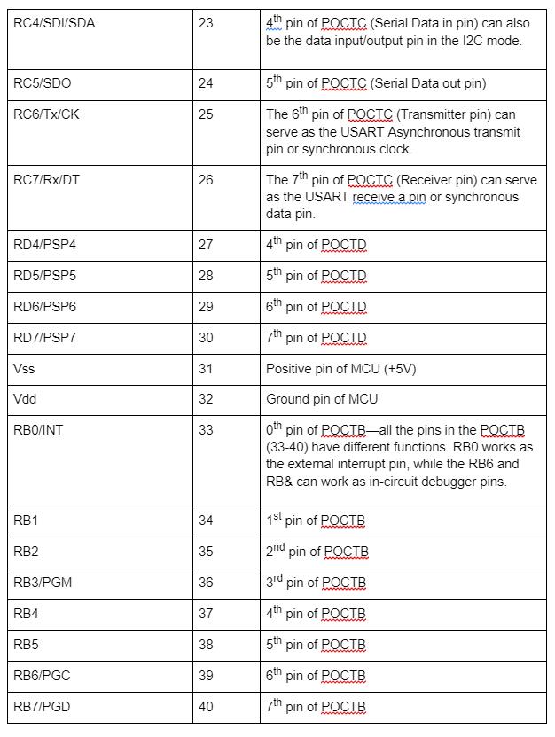
PIC16F877A Microcontroller: The Pinout Configuration
Below is a summary of the PIC16F877A’s pinout configuration:
PIC16F877A Serial Port
The PIC16F877A can work effectively for data communication thanks to its serial port. And like we mentioned earlier, the transmitter pin or RC6/Tx/CK helps you get serial communication. Plus, you can use it to send serial data.
But if you want to receive serial data, the receiver pin or RC7/Rx/DT is ideal.
Compiler for PIC16F877A Microcontroller
Different compilers exist for which you can use with your PIC16F877A microcontroller. So, when you get your preferred compiler, proceed to write your code and assemble it in the device.
Consequently, it will generate a hex file that you can upload in your PIC microcontroller with a programmer.

Circuit Diagram for Flashing LED with PIC16F877A
The circuit diagram for blinking the LED with the microcontroller shows the proper connection (how the LED connects to the PIN). Also, it would help if you had a resistor that would act as the current limiting resistor. And it’s because you can only get a maximum current of 5mA from a single pin.
Here’s how to go about it:
1. Go to the Proteus built-in libraries and pick the PIC16F877A microcontroller and the other components.
2. With a resistor (330R), connect the LED to the PIC16F877A’s pin 16.
3. To get oscillation, attach a 4MHz crystal across the PIC microcontroller’s clock input (pin 13) and clock output (pin14). While you’re at it, connect two capacitors (C1 & C2) on both sides of the crystal.
4. Then, go to the MCLR pin of the controller and attach a pull-up resistor. Afterward, you can tie the other side of the resistor to Vdd.
How Do You Select Your PIC Microcontroller?
Before you select the best PIC microcontroller for your PIC project, it’s vital to answer the following questions:
Are you an expert or beginner? If you’re a beginner, it’s best to go for a microcontroller with broad applications and excellent online support. The PIC18F4520 is a perfect example of a microcontroller in this category.
What’s your system’s operating voltage? If it’s 3.3V the opt for a 3.3V microcontroller. But, if it’s about 5V, go for a 5V microcontroller.
Are you on a budget, and do you want a small size? You can get the small 8-pin microcontrollers.
What modules do you need? The goal here is to choose a PIC with supportive resolution and ADC channels—if you’ll be reading many Analog voltages.
Does your PIC project involve communication protocols like CAN, UART, I2C, etc.? If it does, get a PIC that supports the communication protocol.
How Do You Program the PIC Microcontroller?
There are different ways you can program the PIC microcontroller. You can opt for the obsolete way by using Assembly language. Or use an advanced method. First, get an Integrated Development Environment (IDE), e.g., MPLABX v3.35, to do the programming.
Second, get a compiler, e.g., XC8, to convert your program into HEX files (microcontroller readable form). Third, put your hex file into an Integrated Programming Environment (IPE), e.g., MPLAB IPE v3.35.
Interestingly, you can download and install all this software for free on Microchip.
Applications of the PIC16F877A
You can use the PIC16F877A in some applications like;
- Arduino Module replacement
- Automation projects
- Embedded Systems projects
- Robotics
Final Words
The PIC16F877A is one of the best microcontrollers available on the market that ticks the boxes for ease of use, multiple write-erase functions, and straightforward programming.
And the device is ideal for A/D applications in industrial and automotive industries. Plus, it’s perfect for projects that need multiple communication protocols and I/O interfaces.
What do you think about the PIC16F877A? Do you plan to use it for your next project? Please feel free to reach us for help.