Contents
What is a Push Button Switch?
Push-button switches are open tactile switches that can control a circuit or make a particular action only when you press the button. In other words, it can power up the circuit when pressed and power off the course when released.
Depending on the type of switch, push buttons can operate with a latching action or momentary action.
Also, manufacturers would usually build push buttons with solid and durable materials like plastic or metal–so it doesn’t wear out from continuous use.
Additionally, the surface of a push-button switch can be either flat or a shape that you can quickly press or depress with your finger.
Furthermore, try not to confuse push-button switches with regular switches. While switches have permanent on-and-off positions, push-buttons only have temporary on-and-off functions. Also, when you press a push-button switch, it stays in that depressed state until you press it again to release it.
Push Button Features and Technical Specifications
Here, we’ve listed a push-button switch’s key features and technical specs.
Features
- Tactile feedback provides a crisp click
- It has a 5mS maximum contact bounce
- Its dielectric can withstand up to 250v AC for one minute
- The insert-molded terminal prevents a flux rise in the switch circuit
- Features a snap-in mouth terminal
Technical Specifications
- It uses a tactile feedback mode of operation
- It has a MAX 50mA 24V DC power rating
- Insulation Resistance: 100Mohm at 100v
- Features a .55±0.69 N operating force
- It has a MAX 100mOhm contact resistance
- Operating Temperature ranges between -20 to +70 ℃
- Storage Temperature ranges between -20 to +70 ℃
Push Button Switch Types
The types of push-button switches include:
- Arduino push buttons
- Momentary push buttons
- 2-position push buttons
- Miniature push buttons
- Push to make switch push-buttons
- Tactile push buttons
- PCB push-button switches
- Industrial push buttons
- Dual push-button switches
- Push to break button switches
- Circuit board push button switches
- Panel-mounted push buttons
- Locking push-button switches
- Push to make door button switches

How Does a Push Button Work?
Most push-button switches use the same working principle. Thus, once you place pressure on the actuator or button, it depresses the internal spring and contacts. Plus, this action touches the stable connections found at the bottom of the switch.
Moreover, the process of pressing the switch can either close or open your electrical circuit. Once you press the button again, the internal spring will retract and return the push button connected to its former state.
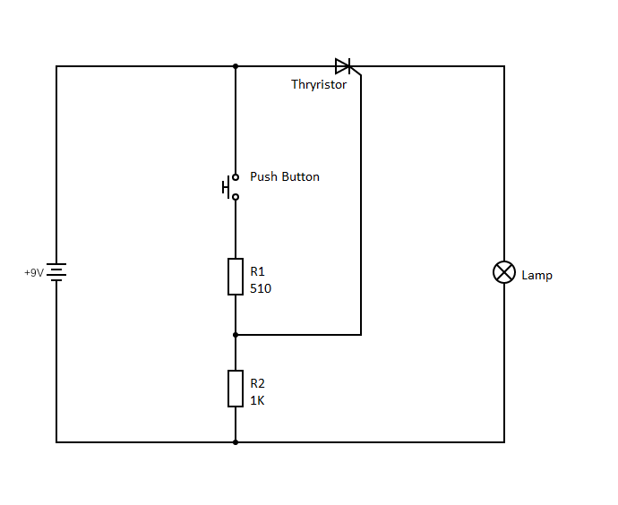
Push-Button Circuit Diagram
Additionally, you can choose between a push-button switch with regular “open contacts” or “closed contacts.”
If you have a momentary switch, you’ll have to maintain the pressure you place on the control to take action. While latching switches, on the other hand, can remain depressed until you press the button again to release it.
How to Wire a Push Button Switch Wiring
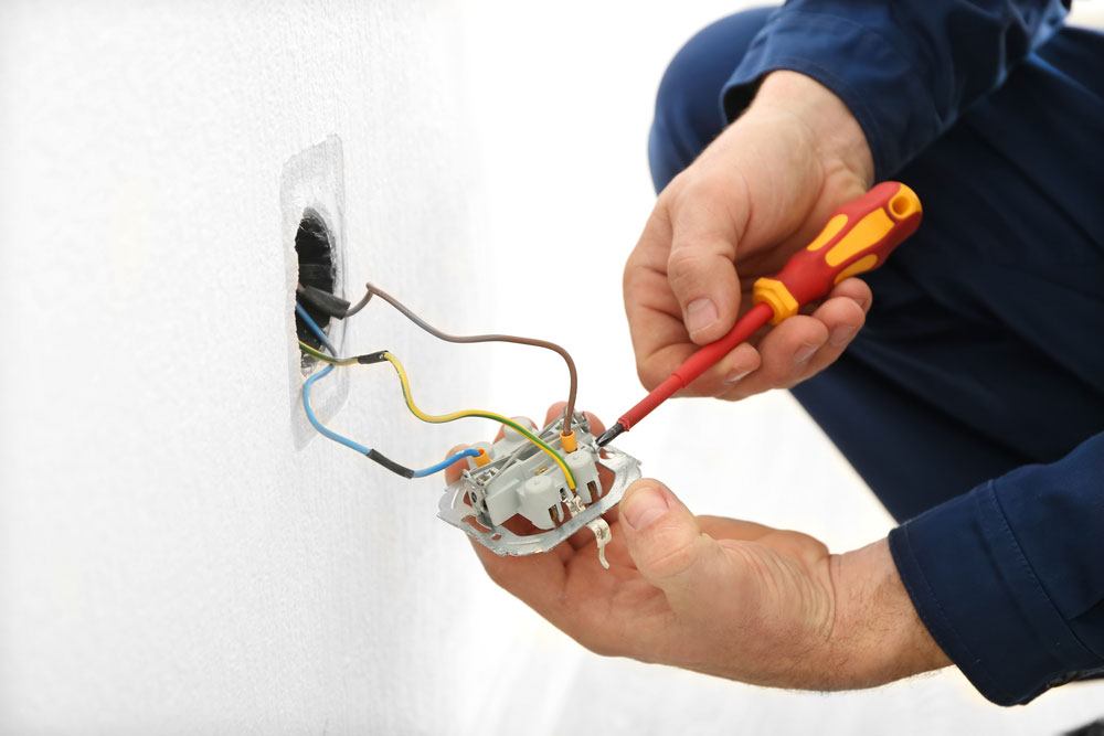
Switch wiring
The push-button we’ll be working with is a 19mm metal push-button switch with self-locking functions and five pins.
The five pins include the normally closed (NC) pin, the normally open (NO) pin, two LED pins, and a C public pin.
For this configuration, the black and red wire stands for the LED wires, the yellow for the NC wire, green for the public C wire, and blue for the NO wire.
To start wiring your push button switch, connect the green C public pin wire to the positive terminal of the power source. Then, make a mutual connection between the red LED wire and the positive terminal of the circuit or appliance you want to control and connect to the blue NO wire.
Next, take the negative terminal of the appliance or circuit and the black LED wire and connect them to the positive pole of the power source.
Afterward, the LED should light up when you push the button to activate your circuit or appliance or go off when deactivated.
Alternatively, you can follow the same steps above, but instead of connecting your mutual connection to the blue NO wire, you’ll connect it to your yellow NC wire.
Wiring a Push Button Switch Wiring with Arduino
When you press them, the push button switches to create connections between two points in a circuit. We’ll turn on a built-in LED connected to pin 13 of the Arduino when you press the button for this project.
What You’ll Need
- Arduino board
- Breadboard
- 10k Ohm pull-down resistor
- Momentary push button switch
- Hook-up wires
Steps
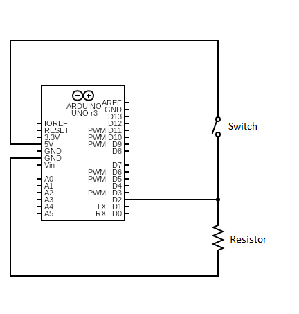
Circuit Schematics
First, connect three hook-up wires to your breadboard. Next, link the first two (red and black) wires to the long vertical rows on the breadboard. This process gives you access to the ground and 5v supply.
Then, use the third wire to connect the digital pin two and one of the push button’s terminals. Afterward, connect that same terminal through your pull-down resistor to the ground pin. Also, join the second button terminal to the 5v supply pin.
Now, it remains open when you don’t press the push button. Thus, there won’t be any connection between the two terminals of the push button. Hence, it means pin two will remain connected to the ground via your pull-down resistor, and we’ll read a LOW signal.
But, when you press the button, it enters a closed state and creates a connection between its two terminals. Then, it connects pin 2 to the 5v supply. As a result, you get to read a HIGH signal.
Alternatively, you can make opposite connections with this circuit. For example, the pull-down resistor will keep the input at HIGH and go LOW when you press the button. In this case, the LED would typically be on and would only turn off once you press the button.
Interestingly, disconnecting the digital I/O pin would cause the LED to blink continuously. Why? Because disconnecting the plug would cause the input to “float.” In other words, it would randomly move between LOW or HIGH signals. For this reason, a pull-up or pull-down resistor is necessary for this circuit.
Push Button Switch Wiring: Applications
- Magnetic locks
- Calculators

- Kitchen Appliances

- Push-button telephones

- Arcade Gaming

- Light switches
- Shower systems and Toilet flushes
- Other mechanical and electronic devices
- Other home and commercial applications
Final Thoughts
Push-button switches offer various ways to use them in your projects. They can even make some activities easier since you have to push a button. You’ll mostly see these button switches turning a device on/off, but they have various other applications.
Some of these push buttons come with LEDs that help indicate the current action. For example, red means stop, while green suggests switching on or beginning an activity. A good example is the emergency stop button, which is generally red and large.
If you have more questions concerning push button switches, feel free to reach us, and we’ll be happy to help.


