
PWM (Pulse Width Modulated Inverters) served as a replacement for older types of inverters. For this reason, they have a wide range of real-time applications. In most cases, companies use them in the creation of power electronic circuits. Pulse Width Modulated Inverters usually use MOSFET, and so they’re commonly called PWM MOSFETs inverters. Indeed, most inverters apply PWM technology to produce AC output voltage for various frequencies and magnitudes. In this article, we will discuss the working of a PWM inverter. Also, we’ll touch on the circuits that you can find in a PWM inverter and explain some PWM inverter types.
Contents
What is a PWM Inverter?
In brief, this is an inverter that uses pulse width modulation technology to operate. Therefore, PWM inverters can retain the output voltage at the rated AC voltage irrespective of the connected load. It works by altering the output voltage frequency width.
The Working Principle of PWM Inverter
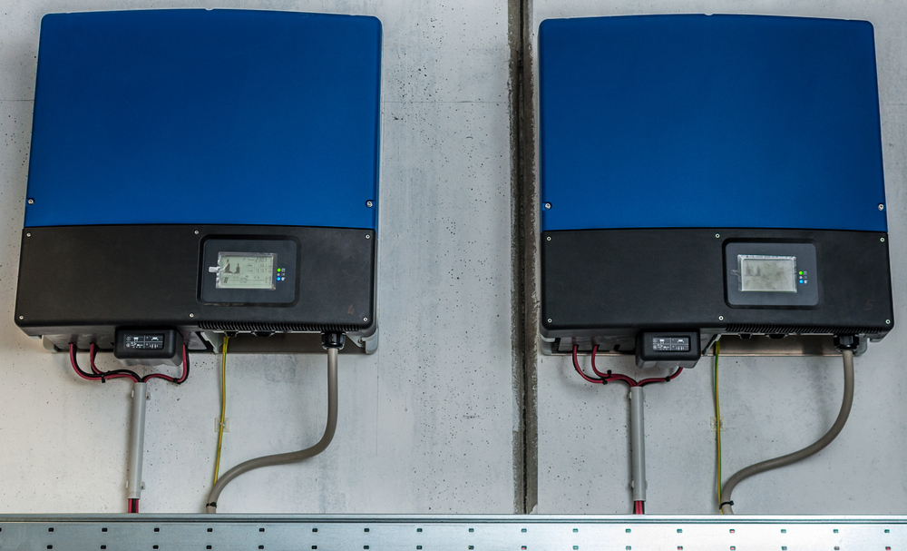
FIg 1: An Industrial Inverter
In conventional inverters, the output voltage changes depending on the load changes. A PWM voltage inverter corrects the output phase voltage using the value of a load that’s connected at the output.
It works by directing back some of the output signals to the PWM controller IC. The PWM controller will use the feedback voltage to rectify the pulse width generated at the oscillator area.
The adjustment in the width of the pulse will eliminate any possible changes in the signal at the output. Thus, the output voltage waveform will remain the same irrespective of any load variations.

Which Circuits are Used in the PWM Inverter?
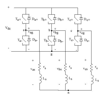
FIg 2: A PWM Inverter Circuit Diagram
Source: Wikimedia Commons
If you observe a PWM inverter circuit diagram, you’ll realize that it uses several circuits. These include:
Battery Charging Current Sensor Circuit
This circuit maintains the current flow used to charge the battery and keeps it at a rated value. It prevents fluctuations that could reduce the battery’s life.
Battery Voltage Sensing Circuit
In some cases, the battery may exhaust. This circuit senses the inverter voltage needed for charging the battery if this happens. It also helps in trickle charging the battery once it’s completely charged.
AC Mains Sensing Circuit
This senses if the AC mains is present. Suppose it’s present, the inverter switches to a charging state. In its absence, it goes to a battery mode state.
Soft Start Circuit
This circuit delays charging for a period of eight to ten seconds after power flow resumes. It protects MOSFETs from high AC power.
Change Over Circuit
It switches the inverter’s modes of operation. It can either be the charging or battery mode, and it’s based on the mains availability.
Shut Down Circuit
It monitors how the inverter operates and shuts it down in case it senses any abnormality. It gets input from several sensor circuits.
PWM Controller Circuit
Here, the circuit controls the voltage at the output of the PWM voltage inverter. In most cases, they use a single IC such as LM494 or KA3535. All the circuits required for the PWM operation are usually incorporated in those ICs.
Battery Charging Circuit
This circuit controls the battery charging process in the inverter. It receives inputs from the mains sensing circuit and the battery sensor circuits.
Oscillator Circuit
In this case, the circuit produces the switching frequency. It’s usually incorporated with the PWM’s IC.
Driver Circuit
Here, the circuit drives the output based on the inverter switching signal. It resembles the preamplifier circuit.
PWM Inverter Types
In brief, a PWM inverter operates under two signals, i.e., the reference signal and the carrier signal. They generate the pulse that’s needed for switching the inverter’s mode by comparing these signals. There are several PWM techniques. These include:
Single Pulse Width Modulation (SPWM)
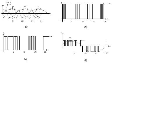
Fig 3: A Graph of SPWM
Source: Wikimedia Commons
In this case, they use a single pulse to regulate the technique in every half-life. Here, It uses a triangular wave as the carrier and a square wave as the reference signal.
Therefore, the generated gate pulse is a result of comparing these signals. But it causes higher harmonics.
Multiple Pulse Width Modulation (MPWM)
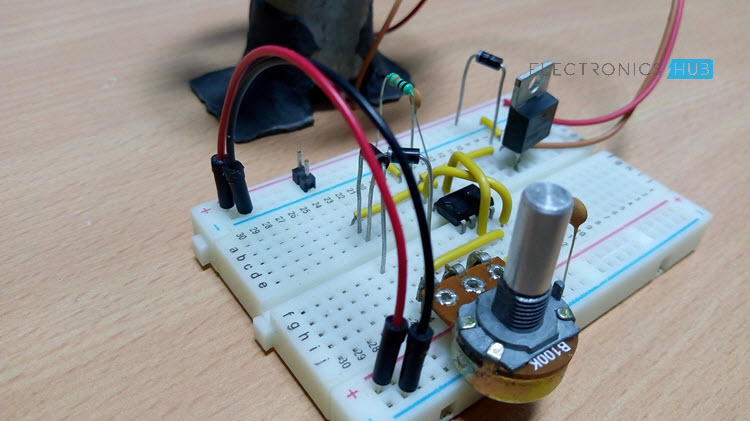
Fig 4: DC Motor PWM Speed Controller
Source: Wikimedia Commons
Here, they use this technique to prevent the problem that may arise from using SPWM. In the same way, multiple pulses replace the single pulse in every half cycle of the output’s voltage. Besides, developers regulate the output frequency by controlling the carrier’s frequency during assembly.
MPWM technology is mainly used by inverters that drive motor control systems with variable frequency. Consequently, this creates many output frequency and voltage adjustments. Generally, this technology improves the waveform’s quality.
Sinusoidal Pulse Width Modulation
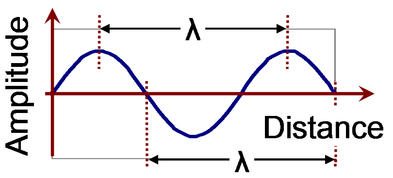
Fig 5: Simple Sine Wave
Source: Wikimedia Commons
In this case, a sine wave replaces the square wave as the reference signal. Meanwhile, the carrier remains as a triangular wave. Thus, the output will be sinusoidal waveforms. On the other hand, the modulation index controls its voltage RMS value.
However, sinusoidal pulse width modulation has two main disadvantages. First, it can’t produce an output voltage that’s as high as the line supply. Secondly, if the output must be fully sinusoidal PWM; it’s essential to include small pulses. Companies do this if the peak modulation wave is almost the same level as the peak carrier voltage.
Adding small pulses may be almost impossible due to the time needed to switch devices on and off. Thus, most industries eliminate the small pulses for efficiency reasons.
Modified Sinusoidal Pulse Width Modulation
Here, the carrier signal is let in in each half-cycle initial and final 60° intervals. As such, this modification betters the output’s harmonic characteristics. The switching reduces the loss and surges the fundamental component.
Conclusion
In conclusion, pulse width inverters use PWM technology to regulate the output at a rated value irrespective of the load. Due to their efficiency, they’ve got many industrial applications, e.g., in DC Motor PWM Speed Controllers. Here, the frequency variation of the applied voltage controls the drive’s speed.
That said, this is our overview of how the PWM inverter works.
However, if you have any questions, feel free to contact us.


