
A remote control tester is a standard device in our households. In truth, you use it to control many electronic appliances like your TV, air conditioner, cable box, etc.
But what happens when the remote goes faulty, and you can’t control these devices anymore? That’s where a remote control tester comes in handy.
Interestingly, you can verify if you need to fix the PCB or replace the remote
control system.
So, in this article, we’ll be explaining different remote control tester projects, answering a few FAQs, and more.
Are you ready? Let’s proceed!
Contents
Op Amp Circuit Remote Control Tester Project
It’s pretty straightforward to construct a remote control tester using opamp. And the components you need for the project include:
- Red LED – 5mm (1)
- C1 – 0.0047µF
- IC741
- Op Amp 741
- Any remote control handset
- Photodiode
- Resistors – 1K (4)
With this in mind, the first step is to use the ordinary opamp 741 for detection. And you can do this by configuring the device as a reference. While you’re at it, use pin 2 (inverting input) as a comparator level.
You can set the inverting input by fixing the connected preset. Then, connect your photodiode across the positive line and non-inverting pin 3.
Further, you can adjust the preset so that the photodiode won’t receive any signal in a normal condition. Consequently, the LED at pin six will remain off.
In other words, all you need to do is switch on power first. Then, adjust your preset back and forth and program it at the point where your LED will stay shut-off.
Next, direct your remote control handset to the photodiode. And press any of the remote control’s buttons. Instantly, you’ll notice your LED blinking in response to the coded IR signals from the remote control.
Remote Control Tester Project Utilizing a Two Transistor Circuit
The components you need for this project include:
- BC 547
- Red LED
- 1N4007
- Any photodiode
- R1 – 100 ohms
- R2 and R3 – 1k
- Power supply (5 to 12 V)
- BC 557
The circuit design of this setup is self-explanatory. First, your photodiode starts conducting when you press the remote control handset button and direct it towards the circuit’s photodiode. Consequently, the photodiode will permit a few mV to pass.
Then, the millivolts or minute electrical signals in the form of millivolts will move to the base of the BC547 (NPN). As a result, the BC547 will respond to the calls and start conducting. But at this stage, the BC547’s amplification will be too low.
Hence, you can connect another form of the BC557 to the collector BC547. And it will help to improve the amplification to a level that will illuminate the indicator LED.
Furthermore, the photodiode releases amplified signals that get a boost to brighten the attached LED that links across the BC557’s collector and the ground line.
As a result, your LED lights will come on and start flashing based on the remote control’s programmed signal code or internal pulse waveform. That said, the 1N4007 ensures that the circuit has a level of filtration from the stray signal that helps your LED to stay off in standby positions.
But if you notice a dim glow in your LED, the ambient light may be incident on the photodiode. And this happens because all forms of white light feature a specific amount of infrared waveform that affects the photodiode’s performance.
Infrared Remote Control Tester With TSOP4838
The components you need for this project include:
- TSOP 1738
- Power supply – 5V
- BC557
- Capacitor – 1µF (optional)
- BC547
- R1, R2 – 100 Ohms
- R3, R4 – 1K, 10K
This project is yet another straightforward one on this list. And you can start by making a connection arrangement of the TSOP IC. With this, you add some transistors, and the circuit will function versatilely.
Interestingly, this circuit isn’t prone to ambient light, sensitivity, range, and noise. Plus, the course has a remarkable detection range. That is, when you direct the remote handset to another wall, your LED will still respond to the reflected rays.
After all, the primary goal of this project is to prove that you can use a simple IR circuit to activate an LED with IR rays from a basic IR remote control system. Also, you can replace the LED with a relay for more complex projects based on the application requirement or user preference.

How to Test a Remote Control
Here, we’ll list the various steps to take to test a remote control—to find out if it’s not very accurate or not.
1. Get the Necessary Material(s) Needed to Run the Test
When it comes to testing a remote, there’s one major thing you need to get things rolling asides from the faulty remote control: a camera.
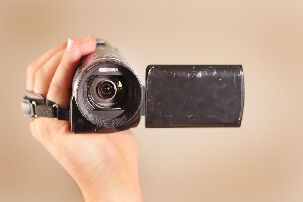
Camcorder Camera
So, you can decide to use a digital camera, camcorder, or even your smartphone camera. With the camera, you can detect the operational status of the remote control.

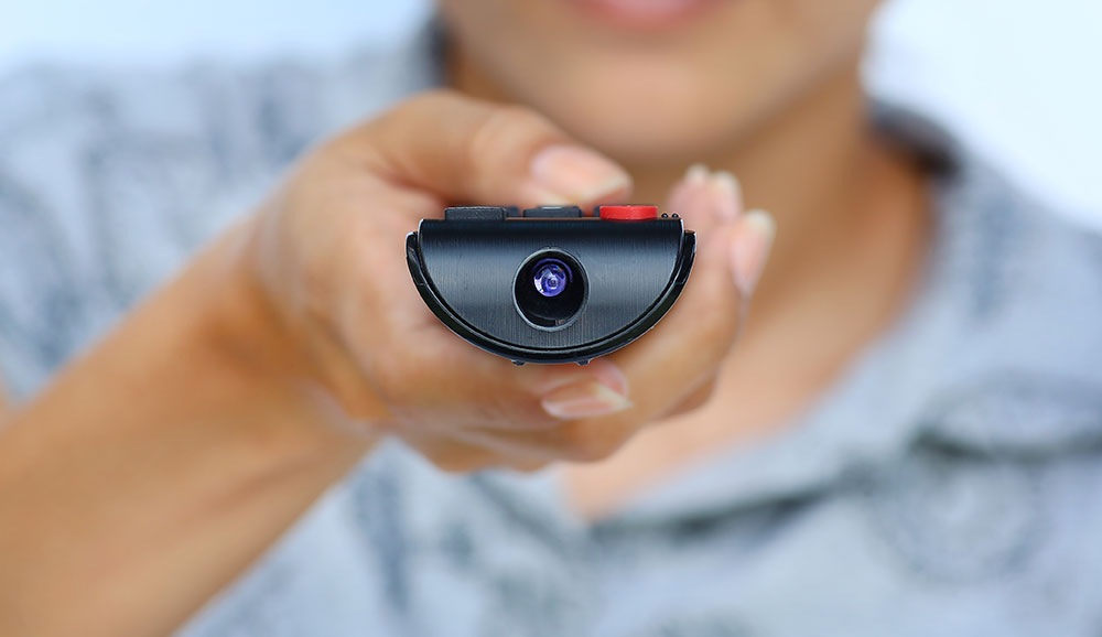
Smartphone Camera
2. Find the Faulty Parts of the Remote Control
After getting the necessary tool for testing, check all the remote buttons to confirm which is working. If you find the faulty switch (s) on the small, mark it with a marker. By doing this, you’re halfway to your troubleshooting or testing.

Man testing faulty remote control
Another way to detect the source of the problem is to check the remote batteries. So, you can confirm by replacing the batteries to see if the remote control responds perfectly. If
replacing the batteries doesn’t work; it’s time to move to the next step: using
the camera.
3. Comprehensive Troubleshooting
Most remote controls come with infrared LEDs that send invisible radio beams to your electronic appliances. So, with a camera, you can see these invisible waves with your
naked eyes. In truth, we can use this particular feature when testing a remote
control.
To run a troubleshoot completely, switch on your camera. Then, face it to the remote’s top end. Next, check the faulty buttons—while you confirm if a light appears in the camera. If
the light comes on, the particular control and infrared LED are functional.

Checking a remote control
So, you can check the status of other buttons and try to notice the light in the camera. If you see
the morning, it means the different remote controls still send signals. But if there’s
no light in your camera, it means none of the buttons are sending signals. In that case, it could be a burnt LED or a connection issue.
4. Finishing Up
In closing, you can eventually tell if the problem with your remote is a button, battery, or LED issue. So, if it’s a button issue or an LED issue, it means you’d have to
replace the remote. But, if it’s battery issues, all you need is a new set of
batteries.
Other Ways to Test Your Remote
Glitching Check I
1. Remove the batteries from the remote compartment.
2. Choose certain random buttons that you’ll press down for 30 seconds.
3. Release your hand and replace the batteries.
4. If the remote starts working, it means you’ve cleared a glitch—by discharging the remote in the previous steps. But if it still doesn’t work, run the next glitch test.
Glitching check II
1. Like the previous step, remove the batteries from the back compartment.
2. This time, click every single button on the remote twice before reinstalling the batteries.
3. By doing this, you’ll be resetting the remote control. Try this final glitch test if the remote still
doesn’t respond.
Final Glitch Check
1. Remove the remote batteries from the back.
2. Press every single button of the remote and hold it down for 10 seconds before releasing.
3. Ensure you don’t skip any button while carrying out this process.
4. Then, replace the batteries, and your remote will reset.
Follow this last step if your remote fails to work after these troubleshooting tests:
Dry Joints Check
Dry joints usually happen when your remote abruptly falls to the ground. So, your small may develop dry joints on the PCB or a loose battery connection. So, here are three steps to check the remote’s status. Please note that you can only carry out this step if you know how to solder a PCB.
1. Unscrew the remote control if there are screws (most times, there are plastic catches—no screws).
2. Thoroughly check all the contacts of the PCB and solder any suspecting joints.
3. By doing this, you’ll be sure of rectifying at least 90 percent of your remote again.
FAQs
How do you test if a remote is working?
The primary check is to confirm the battery status before testing if the buttons or IR LED is functional—using a camera.
How do I know if my remote is RF or IR?
If you see the light in front of the remote when it’s working, it’s an IR remote. But if there’s no light when it’s working, it’s an RF remote.
What is an IR remote tester?
It’s a simple circuit that helps to check if your remote control is functioning or not.
IR LED light of remote.
Final Thoughts
An infrared remote control tester circuit helps confirm an infrared remote control unit’s operation. And the idea of the circuit involves linking a piezo buzzer to an IR receiver IC. Plus, this circuit has a range of several meters, and it’s pretty sensitive.
Also, if you want a device that can demodulate, accept, and amplify your remote control’s IR signal, use a TSOP IC. Consequently, you’ll have an excellent detection range.
So, what do you think about the topic? Do you need help with doing any of the projects we described? Please feel free to contact us.


