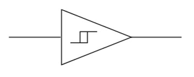
Schmitt Trigger, known initially as the thermionic trigger, has been around for decades. So far, it has contributed to life-changing technological advancements such as tracking switching among two voltage states. It is a comparator or differential amplifier that has an additional hysteresis to offer noise immunity. But even without the hysteresis, it can solely act as a comparator that makes clean digital pulses.
Today, we will design a Schmitt trigger circuit then explain how it works. Additionally, we will highlight several areas whereby you can apply the Schmitt trigger circuit.
Contents
1.What is a Schmitt Trigger?
Briefly, it is a regenerative comparator. It uses positive feedback to implement hysteresis voltage or change sinusoidal input to square wave output. Often, the output voltage of the Schmitt trigger acts as the reference voltage of input waveforms. It functions to convert noise from its analog input signal form to digital signal.
Schmitt trigger can also be a bi-stable circuit. The bistable circuit has steady high- and low- output voltage swings once the input reaches the desired threshold level.
2.Types of Schmitt Trigger
Undoubtedly, there are several logic Integrated Circuits with Schmitt triggers as one of the components. In our case, however, we will base our interest on the DIY Schmitt trigger we’ll have.
The types include;
- An Operational Amplifier-based Schmitt trigger, and
- A transistor-based Schmitt trigger.
Further explanation on the above types is under the common Schmitt triggers circuit.
3.How Does a Schmitt Trigger Work?
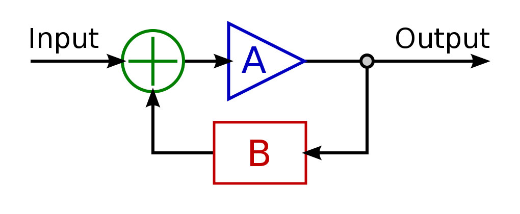
A Schmitt trigger uses a positive feedback concept to achieve its functioning. In other words, it will take an output sample then feed it back into the input source. In this way, the output will have a reinforcement.
(positive feedback explanation).
The reinforcing helps in making the comparator output settle on its state at will. Also, it ensures the state is constant at the stipulated level.

4.Common Schmitt Triggers Circuits
Schmitt Trigger Using Transistors
We will use two transistors (the essential components), and other basic external components for this Schmitt trigger circuit to set up the block diagram.
Operation of the circuit
First of all, T1 won’t conduct when VIN (input voltage) is at 0V. On the other hand, the Vref (voltage reference) has a 1.98 V, which will allow T2 to conduct.
Further on, when we proceed to node B, we can treat the circuit as a voltage divider then use the formulas below to calculate the voltage with the component values;
VIN = 0V, Vref = 5V
Va = (Ra + Rb/Ra + Rb + R1) x Vref
Vb = (Rb/Rb + R1 + Ra) x Vref
As we have noted, the 1.98 conducting voltage of T2 is low. Also, the base voltage at the terminal of the transistor is 1.28V, which is higher than the transistor emitter terminal voltage at 0.7V.
Thus, increasing the circuit input voltage can cross the T1 value and make it conduct. Subsequently, it’ll lead to the dropping of T2’s base voltage. A shorter conducting period of the T2 transistor then increases the output voltage.

Schmitt trigger using transistors
Next, the circuit input voltage at the T1 base voltage of the terminal will start refusing. In the process, the base terminal voltage will go beyond 0.7V of the transistor’s emitter terminal, then cause the deactivation of the transistor.
The whole procedure is dependent on the emitter current refusing to a point where the transistor finds a mode of forward-active. Later, both the base voltage at the terminal of T2 and the collector voltage will rise.
However, sometimes there will be little current flowing through T2, and the current is capable of turning off T1 and dropping the emitter’s voltage. Under such a circumstance, you will drop the circuit input voltage to about 1.3V to deactivate T1.
Finally, you will have two threshold voltages at 1.3V and 1.9V.
Operational Amplifier-based Schmitt Trigger Circuits
The Op-Amp-based Schmitt trigger circuits have two major divisions; the non-inverting input and inverting Schmitt triggers.
Inverting Schmitt Trigger Circuit
For the inverting Schmitt trigger input, you will apply the inverting terminal of the operational amplifier (Op-Amp). Furthermore, the output generated from the inverting mode is of opposite polarity, and you’ll need to apply it to a non-inverting terminal to get positive feedback.
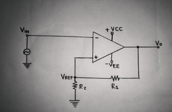
Inverting Schmitt trigger circuit
Explanation and formula of the inverting Schmitt trigger circuit above;
VREF lesser than VIN results in a -VSAT comparator output. Contrarily, if -VREF is slightly greater than VIN (more negative), the output will be VSAT. Therefore, the Vo (comparator output voltage) will either be -VSAT or VSAT. But you will have to control the circuit input voltages with R2 or R1 to regulate the state changes of the circuit.
Values of -VREF and VREF formulation;
- VREF = (VO * R2) / (R1 + R2)
2. VO = VSAT, therefore,
3. VREF = (VSAT * R2) / (R1 + R2)
4. -VREF = (VO * R2) / (R1 + R2)
5. VO = -VSAT therefore,
6. -VREF = (-VSAT * R2) / (R1 + R2)
Sometimes, you’ll find VREF referred to as Upper Threshold Voltage (VUT), whereas -VREF is the Lower Threshold Voltage (VLT).
Circuit of a Non-Inverting Schmitt Trigger
In the second mode of the Op-Amp-based Schmitt trigger circuit, you apply the circuit input voltage in the non-inverting input terminal of the operational amplifier. Afterward, the emitter resistor R1 will allow the output voltage back to the non-inverting terminal circuit.
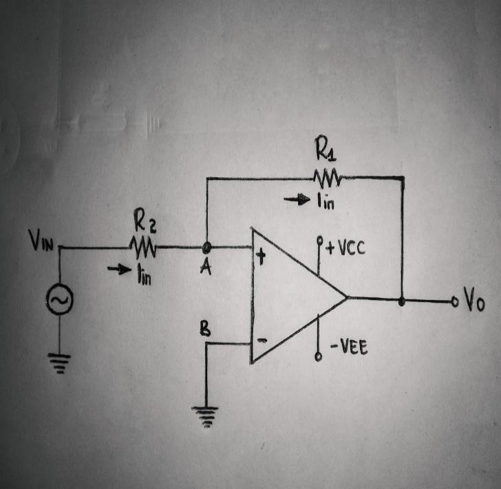
Non-inverting Schmitt triggers circuit
Let’s say the output voltage was at VSAT in the beginning. The output voltage will be at the same saturation level as long as VLT is higher than VIN. If, later on, the circuit input voltage surpasses the lower threshold voltage level, then the output status will change to -VSAT. You can also vary the bias voltage in series to get desired reference voltage values.
Finally, the output will be constant at the -VSAT state until the circuit input voltage rises above the upper threshold voltage.
5.Applications of Schmitt Triggers
You will find the Schmitt triggers circuit in several applications such as;
- First, in the switch debounce circuit.
- Then, you can use a Schmitt triggers to implement a relaxation oscillator especially, in designs with a closed-loop -ve response.
- Also, you can use them in function generators and power supplies.
- In addition, the trigger circuit changes sine wave to square wave.
- Finally, you can incorporate them in digital circuits as signal conditioning to help in removing signal circuits.
Summarize
To summarize, today’s article gives a detailed insight on Schmitt Triggers, its operation, basic circuit structure, and also some of its applications.
Even with the trigger’s high efficiency, it’s best to have some preventive measures such as. Driving an Op-Amp into rails. There will be more power consumption, and so, you’ll need a high-power source. Despite the limitation, you will get rid of noisy signals and a reduced number of multiple output transitions.
Having trouble setting up your circuit or stuck on a project? Contact us for more details.


