The Solder Mask
For the generation of the electrical components, the process of assembly is needed. For this process, dedicated machinery is required. The assembly process is achieved by soldering the details over the circuit board. For the prevention of the circuit boards from being short-circuited accidentally, the solder mask is being used by the manufacturers of the printed circuit boards, separating two nets apart. The standard color of the solder mask used is green. Moreover, blue or red is also used.
Overlay
The overlaying is when the manufacturing company prints the information of the design onto the solder mask. This process is done to simplify the process of assembly and the repair and verification process. The overlay is printed onto the test points and the orientation position and referencing the components placed on the circuit.
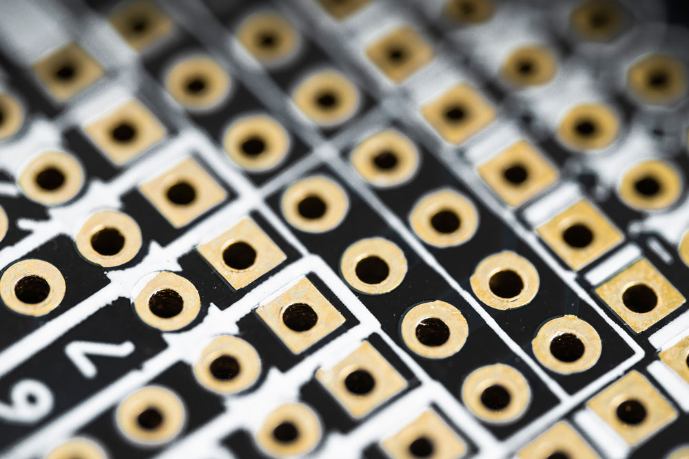

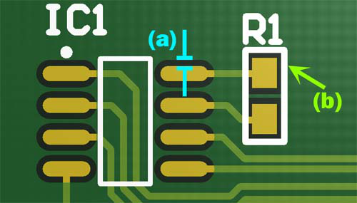
The Pads
The pads are the trim surfaces of the copper on the circuit boards, allowing the soldering of the components onto the board. The places are the pieces of copper where the tops of the members are lied to be sold.
The Copper Tracks
The copper tracks are the paths of copper for the conduction of the electrical components being sold to the circuit board.