Microcontroller development is a cardinal process in electronics assembly. But the input of serial protocols and communication interfaces facilitate this undertaking. In this article, we intend to exhaustively explore serial communication protocols such as SPI I2C UART interface and UART. We’ll analyze the serial protocols’ features, upsides, downsides, and examples.
Contents
1. UART Interface
What is UART?
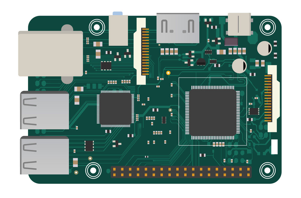
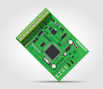
Figure 1: A UART protocol on Arduino
Universal Asynchronous Reception and Transmission (UART) is a serial communication protocol that facilitates host communication with auxiliary devices. Primarily, it enables serial data transmission. Besides, it’s capable of asynchronous communication and bidirectional transmission.
The simple protocol also features two data lines: handling transmission (Tx) and other signal reception (Rx). Usually, signal transmission is via digital pin 0, while the reception is through digital pin 1.
Also, it aids in synchronizing the management of a computer and external serial devices.
How does it work?
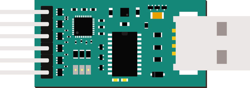
Figure 2: A DIY electronic USB UART board
Essentially, UART manages signal communication between two devices via the following means:
- Simplex
- Half Duplex
- Full Duplex
Simplex involves unidirectional data transmission, while half-duplex means non-simultaneous communication between two devices in either direction. Lastly, a full duplex entails simultaneous data transfer in either direction.
Generally, after connection, there’s data transfer from the transmitting UART’s data line to the receiving UART. It happens via the following principle;
- First, the Transmitting UART will convert a master device’s parallel data to a serial form for transfer to the receiving UART. Similarly, the receiving UART changes the serial data to parallel data for use by the connected receiving device.
- Since UART entails asynchronous communication, it features no clocks. Thus, the UART will generate start and stop bits to indicate the beginning and the end of a message.
- The two UARTs must function at the same BAUD rate or UART data transmission speed. Ideally, this is to ensure accurate timing of the data bits as a difference of more than 10% makes the data useless.
UART Working Protocol
Data Transmission and Receiving
- For transmission, the transmitting UART requires to receive data from a data bus such as a CPU.
- Next, it adds the three bits, namely, the start bit, parity bit, and stop bit. The three will form a data packet transmitted to the receiving UART via the TX pin.
- Data transmission stops after the exhaustion of data in the transmitting UART.
Interrupt Control
Data interrupts are handy in automatic buffer content sending. You may prompt an interrupt control in case of the following scenarios:
- First, use it when you experience a FIFO (First in, First out) Overflow Error, line break error, frame error, or a Parity Error.
- Also, activate it during data receiving, sending, or while you’re receiving timeout.
FIFO Operation
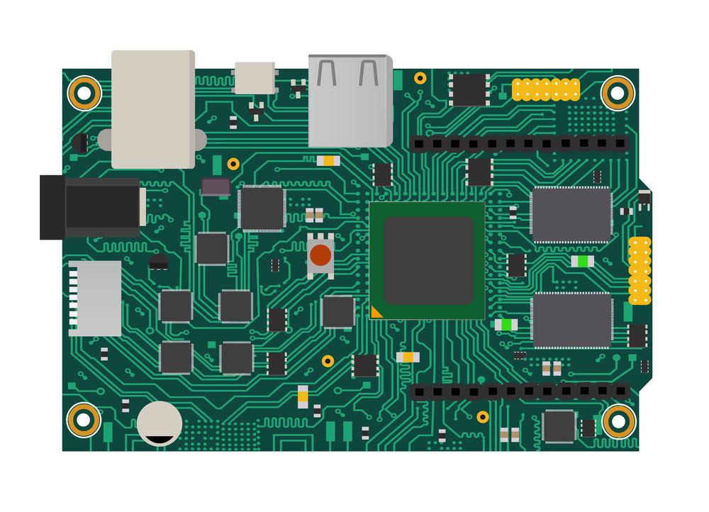
Fig 3. A UART interface on Arduino
Stellaris family UART Modules feature two 16-byte FIFOs, one for data reception and the other for transmission. Also, you can configure them at various depths to deliver different interrupts. For instance, you may have 1/8 depth, 1/4 depth, 1/2 depth, etc.
Working process of transmitting FIFO
- Primarily, data transmission commences after data entry. Also, since it’s time-consuming, data entry is continuous until the transmitting FIFO is full.
- Once full, you must stop data entry lest you lose all the new data.
- Next, the transmitting FIFO sends the data bit by bit until it’s empty. Finally, the transmitting FIFO will create an extra slot.
Working process of receiving FIFO
- After receiving data from the abovementioned step, the hardware stores it in the receiving FIFO. Ideally, receiving and erasure data by the receiving FIFO program is an automatic process. Thus, there shall be enough space in the receiving FIFO.
- It also features a transceiver FIFO that is essential in solving CPU inefficiency issues. Further, it aids in resolving the issue of frequent UART transceiver interruptions.
- Lastly, FIFO has no data loss as it seals all the probable loss avenues beforehand.
Loopback
The UART has an internal loopback for debugging and diagnostics about where the RX input will receive the sent data.
Serial Infrared Protocol
UART features an IrDA Serial Infrared (SIR) operating as an encoder/decoder module. It is handy in translating a half-duplex serial SIR interface and an asynchronous UART data stream.
Moreover, the serial communications protocol delivers a decoded input and a digitally coded output to the UART.
Advantages of Using UART
- The simple communication protocol is a well-documented module that is also easy to use.
- Secondly, it doesn’t require a serial clock line.
- Thirdly, it has a parity bit that enables error checking.
Disadvantages of Using UART
- The UART interface has a data frame size limitation of 9 bits and has slow transfer speeds.
- Besides, it’s incapable of using many master systems and slave devices.
- Also, it has a compulsory baud rate of within 10% as a shield from data loss.
- Fourthly, it generally has slower speeds during data transfer between devices.
UART Examples in Microcontrollers
- UART Seeeduino V4.2
- USB to UART 5V
- Base Shield V2
- USB CP2102 Serial Converter
2. I2C Interface
What is I2C?
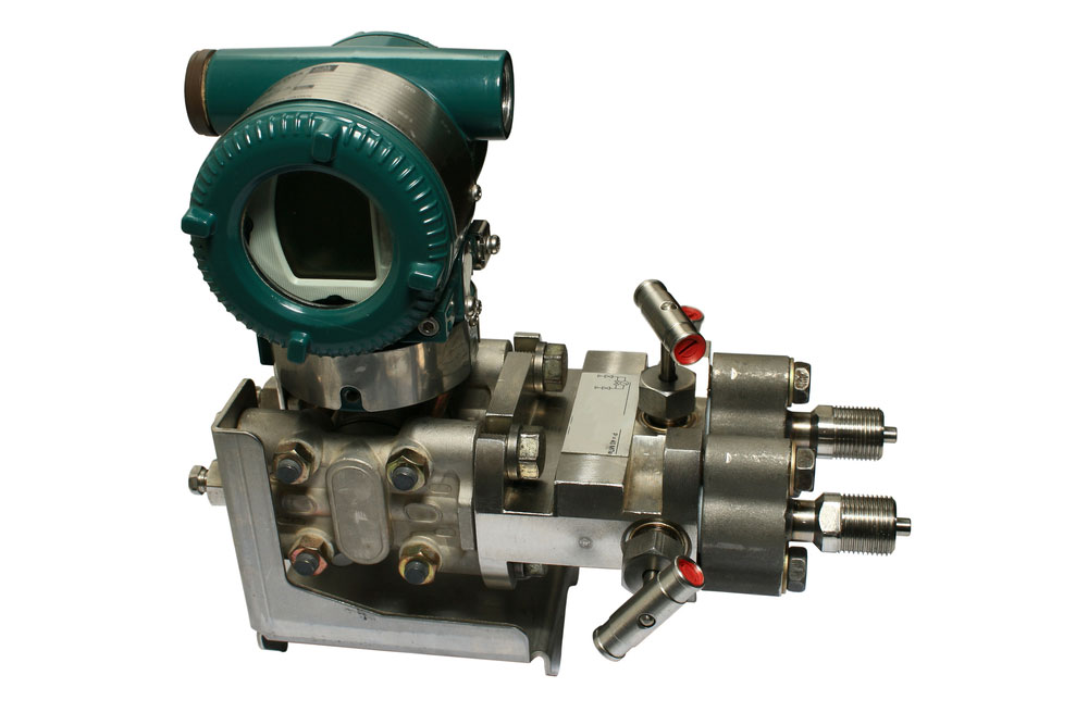
Figure 4: A Differential Pressure Sensor uses I2C
The Inter-integrated-circuit (I2C) communication protocol resembles the UART. But, while UART is designated for PC-device communication, I2C is useful in sensors and module applications.
Besides, the bidirectional two-wire synchronous serial bus can connect multiple devices without compromising the communication pathway. It is thanks to its shared bus and address system property.
But this feature comes at the cost of having relatively slow communication between devices compared to an SPI. Its speed relies on external noise, wire quality, and data speed.
Lastly, the two-wire interface enables connection to low-speed devices such as EEPROMs, Analog/Digital converters, and microcontrollers.
How does it work?
An I2C protocol features two lines: the serial data line acceptance port (SDA) and a serial clock line (SCL). The SCL facilitates transmission synchronization while SDA represents the data line for sending and receiving data bits.
During the transfer, the master device prompts the bus data transmission. Simultaneously, it generates a clock that opens the transferring device. In this scenario, the addressed device in the transmission is a slave device.
Noteworthy, the master device and slave device do not have a constant data transmission rate. Rather, their relationship relies on data transfer direction at the transmission time.
Also, the single master device must inform the slave select device before initiating a data transmission. Similarly, it needs to inform the slave before receiving data from the slave.
It’s also important to connect a pull-up resistor to the I2C power supply for optimal functioning.
I2C Working Protocol
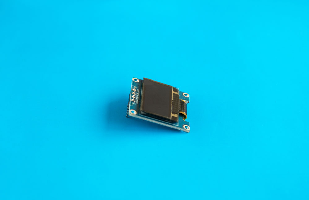
Figure 5: A pin 0.96 inch OLED 128X64 OLED Display Module IIC I2C
Data Transmission Method
The connection procedure is as follows:
- The master output will send a transmitting signal to the connected slaves, primarily by switching the SDA line from high voltage level to low. Next, it’ll switch the SCL line from high voltage level to low.
- Then, the master sends 7-bit or 10-bit addresses and reads/writes bits to each of the slaves.
- Thirdly, the slaves compare the address to their own. If it matches, it will return an ACK bit, switching the SDA line to low. However, if they don’t match, the slave will leave the SDA line on a high.
- Next, the master sends the data frame or receives it (depending on the matching addresses). Then, after complete data transmission, the receiving component returns an ACK bit to the data sender. It is to acknowledge a full transmission.
- Finally, the master switches the SCL to high and then the SDA to communicate the end of the communication.
Clock Synchronisation
Every master must generate its clock signal in the SCL line for data transmission. Besides, it is only during the clock’s high period that data remains valid in an I2C transmission.
Transmission Modes
It primarily transmits via two means, namely:
Quick Mode
Devices on fast mode receive and transmit data at the rate of 400kbit/s. Also, a fast mode I2C bus can significantly suppress glitches, and their output features a slope control function.
High-Speed Mode
An I2C bus at a high-speed mode will transmit data/ receive at a bit rate of 3.4 Mbit/s. Thus, it features faster data transmission rates than the erstwhile quick mode.
Advantages of I2C
- It features a significantly limited number of pins/signals even when you’ve connected numerous devices on the master.
- Secondly, an I2C device offers flexibility thanks to its multi-master and multi-slave capability.
- Also, it’s simple to use as you only need two bidirectional wires to make a connection to numerous devices.
- In addition, it offers extensive adaptability and can also support numerous masters.
Disadvantages of I2C
- It has a relatively slow speed and must use pull-up resistors, unlike the SPI, which only needs push-pull resistors. Also, its open-drain design curtails its speed.
- Besides, the resistors occupy space which is of immense essence in PCB assembly.
- It’s not easy to use when you’ve connected numerous devices.
Examples of I2C in Microcontrollers
- Raspberry Pi’s 4-Channel 16-Bit ADC
- I2C Hub (6 Port)- Grove
- I2C Driver/Adapter
- I2C Arduino
3. SPI Interface
What is SPI?
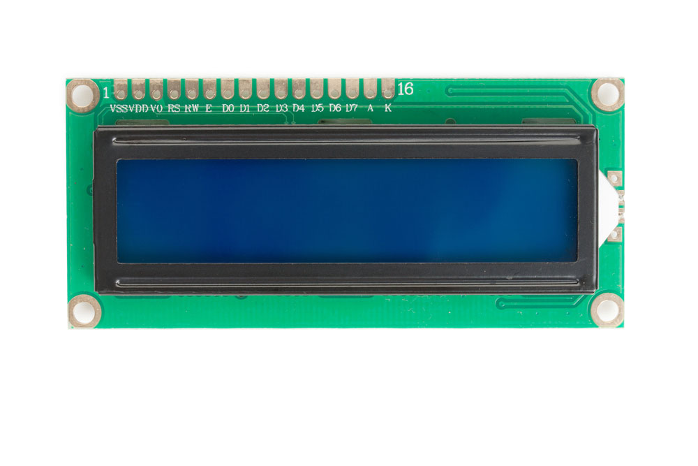
Figure 6: An SPI Interface is handy in Display Modules.
The Serial Peripheral Interface (SPI) is designated for use in microcontrollers. Also, since it functions in a full duplex, it allows simultaneous data transmission and reception.
The SPI is relatively faster than I2C, with a data transmission rate of at least 8 bits. Primarily, this module’s simple protocol enables faster data rates. Thus, it’s important in applications that require speed, such as display modules and SD Cards.
It’s also essential in applications involving a sudden change of information, e.g., thermometers.

How does it work?
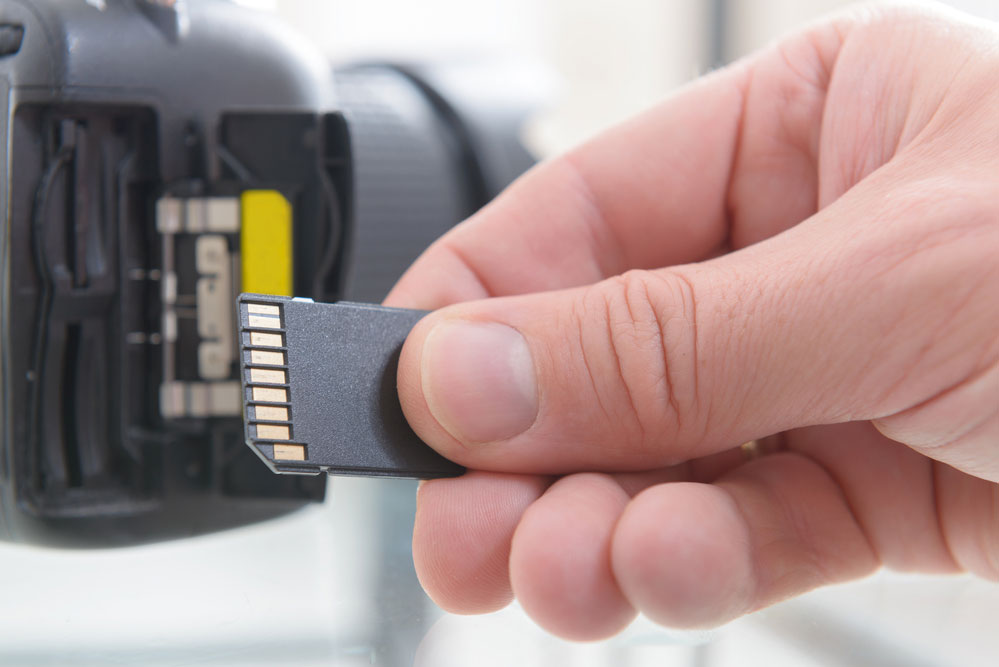
Fig 7: SD Cards utilize SPI
An SPI form of device will operate in either of the following two ways:
- First, it selects the device with a Chip Select line. Note that each device requires its unique Chip Select line.
- Alternatively, it also functions via daisy chaining.
You can connect as many devices as you want in an SPI interface. However, in most cases, you’ll be limited by the available hardware select lines. Lastly, during point-to-point communication, the module doesn’t need to address operations.
SPI Working Protocol
SPI functions via four ports, namely:
- Master Data Output, Slave Data Input (MOSI)
- Master data input, slave data output (MISO)
- A clock signal (SCLK)
- Slave-enabled signal (NSS)
When using a multi-slave system, each respective slave demands a unique enable signal. This requirement complicates the hardware requirement as compared to an I2C communication.
Also, the SPI interface features two shift registers. It allows synchronous serial data transmission between a single master device, such as a CPU, to peripheral devices.
Advantages of using SPI
- It is simple to use since, unlike an I2C, it lacks a complex slave addressing system.
- Secondly, it’s the fastest protocol of all the serial interfaces we’ve covered (Faster than UART and I2C).
- It doesn’t have start and stop bits like in UART communication. Thus, it allows continuous data transmission without interruptions.
- Lastly, it features separate MISO and MOSI lines that enable simultaneous sending and receiving of data.
Disadvantages of using SPI
- Most of its Pin ports are occupied, which limits the number of devices you can connect.
- Also, it lacks a specified flow control, and unlike in I2C, there’s no mechanism to acknowledge data has been sent/received.
- It requires the use of 4 lines, as we’ve highlighted above, and unlike in UART, it lacks an error check mechanism.
- Fourthly, it also has a single master.
Examples of SPI in Microcontrollers
- SPI Seeeduino V4.2
- SPI Driver/Adapter-Easily Driver SPI Devices
Comparing UART, I2C, and SPI
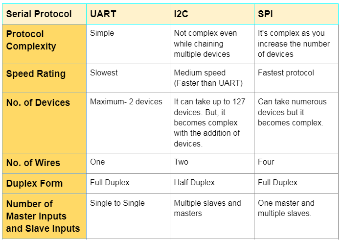
Which of these communication peripherals is the “best”? UART, SPI, or I2C?
There are no superior communication peripherals out of the three, as each has its key upsides and downsides. Thus, choose the best fit protocol depending on your project. For instance, SPI would serve you best if you are looking for speed.
But if you want to connect numerous devices without having a complex array, go for I2C.
Conclusion
We’ve laid bare all the key insights you need to know about UART, I2C, and SPI communication interfaces and their various transfer rates. Also, we’re here to answer any queries about the communication protocols. Reach out to us, and we’ll come to your aid immediately.