Stripline vs. microstrip comparison always comes up because they are the two types of PCB transmission lines.
Also, each transmission line comprises a signal trace and reference plane(s). But what are the differences between these PCB lines?
In truth, the primary difference between strip lines and microstrips is their location. But that’s not all we’ll look at today.
Also, this article will highlight the differences between microstrip and stripline transmission lines and explore each one’s advantages.
Are you ready? Let’s go!
Contents
- 1 What are Striplines in PCBs?
- 2 What are Microstrips in PCBs?
- 3 Stripline vs. Microstrip: What’s the Difference?
- 4 What Are the Pros and Cons of These Routing Styles?
- 5 What Is the Rate of Losses For Striplines and Microstrips?
- 6 What Are The Routing Techniques To Use For Microstrips and Striplines?
- 7 Final Words
What are Striplines in PCBs?
PCB with transmission lines
You can route strip lines on the inner layers of your PCB design, surrounding it with a single environment (the PCB material). In truth, applying these transmission lines works for multi-layer PCB designs, where ground planes above and below back the signal trace.
For a stripline, the design provides the high-frequency signal trace’s current a return path above and below the ones on the ground planes (or power planes). As a result, PCBs with striplines keep the high-frequency signal inside, leading to lesser emissions and shielding against fake signals.
What are Microstrips in PCBs?
Microstrips are planar transmission lines more prominent in microwave and RF PCBs. Unlike strip lines, you can route microstrips on the PCB’s surface, surrounding them with two environments: PCB material and air.
Also, microstrips comprise strip conductors (land) on dielectric substrates. Further, a ground plane backs it up and radiates when the space between it and the strip increases.
Microstrips have a dominant propagation mode, which we call Quasi-TEM (Transverse Electromagnetic). But what does this mean?
The cross section’s characteristic impedance, field variation, and phase velocity become frequency-dependent.
Stripline vs. Microstrip: What’s the Difference?
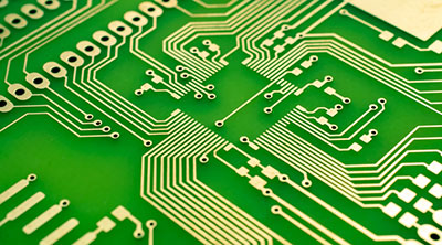
Printed circuit board
While we can’t say one routing style is better, the differences help indicate which one to use for different applications. So, let’s look at these differences in multiple areas.
Location
As mentioned earlier, the primary difference between microstrips and striplines is their location. While striplines are in inner layers (usually between two reference planes), microstrips stay on the PCB’s outer layer.
Usage
Generally, you can choose between strip lines and microstrips when routing your designs. But here are some things to consider before choosing between these routing styles.
- Striplines are your go-to routing style if your application requires high-density managed impedance. Why? A stripline has an increased density for controlled impedance routing than a microstrip.
As a result, a thin stripline will provide the same impedance you can get from a wider microstrip.
- While you won’t need any routing styles if your PCB design has short routes between close components, you can work with microstrips if your application needs impedance control.
- Stripline routing is not an ideal choice for ultra-high frequencies. Sadly, the Via accessing the inner layer will act like a separate transmission line, allowing parasitic capacitance around it to create signal losses and impedance continuity.
- You can also use strip lines if you need high isolation between your design’s layers. The routing style can create interlayer isolation that’s impossible to achieve with microstrips.
However, this design style doesn’t promise high isolation between strip lines on similar layers. Therefore, you’ll need to address crosstalk before proceeding with this design.
- Lastly, applications with any high-pin count component must combine both routing styles.
Characteristic Impedance
A stripline’s characteristic impedance depends on the strip’s center conductor & ground plane’s cross-sectional geometry and dielectric constant.
Further, a stripline’s characteristic impedance decreases as the strip width (We) increases. Here’s the formula showing a stripline’s characteristic impedance:
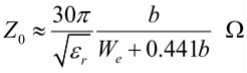
Note: “We” stands for the effective strip width, and “b” represents the spacing between two planes.
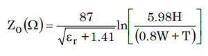
On the other hand, a microstrip line’s characteristic impedance changes with every frequency increase.
However, we must note that the IPC microstrip’s equation shows high accuracy between 100 and 50 Ω. Here’s the equation for a microstrip’s characteristic impedance.

What Are the Pros and Cons of These Routing Styles?
Pros
Both stripline and microstrip have their respective advantages. Let’s take a quick look at each style’s pros.
Stripline Advantages
- Striplines can shield and protect signal traces from invasive frequencies.
- The routing style’s performance will increase above 50MHz.
- Striplines also provide low impedance, leading to lesser emissions and crosstalk.
- Stripline routing styles offer better EMI characteristics.
Microstrip Advantages
- Microstrips are ‘open’ line structures, making connecting components to the PCB’s surface incredibly easy.
- You can also pack microstrips together on high-density channels with minimal crosstalk, making it the go-to for RF and microwave IC designs.
- Microstrips have planar topology, giving them slight immunity to PCB manufacturing process tolerances.
- Also, they provide faster propagation times.
- Lastly, this routing technique offers heat sinking and mechanical support simultaneously.
Cons
Likewise, each routing style has its disadvantages. So, let’s take a closer look.
Microstrip Disadvantages
- Although microstrips are affordable and offer compact sizes, they’re lossier than striplines, coaxial lines, CPW, and waveguides.
Stripline Disadvantages
- Striplines have embedded signal traces, making them tricky to debug. In other words, PCB troubleshooting and prototyping will be more difficult than usual.
- Striplines are tricky to decouple.
- Proper matching will only result in low impedance.
What Is the Rate of Losses For Striplines and Microstrips?
Unfortunately, both routing styles are not immune to losses. But microstrips may experience more losses than striplines.
First, straplines can create losses from finite conductivity in their conductors, magnetic resonances, and dielectric dumping phenomenon & finite resistivity.
On the other hand, microstrips experience losses from magnetic loss relevant to magnetic substrates, the line conductor’s finite conductivity, substrate finite resistivity, dumping phenomenon, and radiation effects. And the radiation effects depend on the following factors:
- Substrate thickness
- Frequency
- Dielectric constant & circuit geometry
What Are The Routing Techniques To Use For Microstrips and Striplines?
Apart from the differences discussed above, PCB stripline and microstrip designs have routing differences.
Different Types of Microstrip Routing Techniques
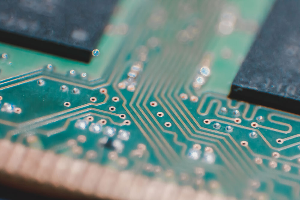
Microstrip Routing
You can route your transmission lines on your PCB’s outer layer for this technique. But the design’s modeling depends on trace width, thickness, substrate height, and dielectric type.
Microstrip Differential Pair Routing
Although this technique utilizes the same arrangement as the standard microstrip routing, it’s more appropriate for differential pairs. Also, this technique is a more complex model because of the extra trace spacing required for the differential pairs.
Embedded Microstrip Routing
Embedded routing is similar to the standard microstrip technique. But it has an additional dielectric layer above the transmission line.
Coplanar microstrip routing
In this microstrip routing technique, you can route the signal traces parallel to two ground planes. Further, these ground planes naturally shield the signals from interference on the PCB.
Different Types of Stripline Routing Techniques
Stripline Routing
You can route the traces on the PCB’s internal layers for stripline routing. But similar to microstrips, its modeling depends on the trace width, thickness, dielectric type, and substrate height.
Also, it relies on the calculations made for the trace embedded between two grounding planes.
Coplanar Stripline Routing
For this technique, you’ll route the signal trace internally and in parallel to two ground planes.
Broadside-coupled stripline routing
You can use this technique for routing internal layers with differential pairs.
Final Words
Before deciding between microstrip and stripline, we recommend getting the advice of experienced manufacturers.
If your application pushes the boundaries of data centers, telecom, and low-power embedded systems, It will pay off with professionals.
While we can’t say one routing style is better, each one excels at its respective applications.
Do you have more questions? Feel free to contact us, and we’ll be happy to help.