
Dangerous and lethal, a stun gun circuit stores voltage that, when hitting a target, causes severe pain. Because of that effect, these provide stun guns and other device applications to enforce security measures. And handling this taser circuit sounds risky without being informed of the potential consequences. After all, you will not want to feel the electric shock’s impact.
The complexity can seem overwhelming. At WellPCB, we put together an in-depth guide. After reading, you will gain considerable knowledge of this circuit. So let’s take a look!
Contents
1. What is a Taser Circuit?
A taser circuit produces a high AC voltage and low current due to the high impedance. The charge contains a lot of pressure but lacks intensity. Deployed in stun guns, these circuits distribute a cycle of electricity to an intended target. In effect, it renders the attacker temporarily paralyzed or stunned upon contact while putting them in considerable pain.
2. Type of Taser Circuit
Three taser circuits exist, multiplier, spark gap, and thyristor. A multiplier taser, which takes in DC power, consists of high-voltage capacitors, diodes, and a transformer. Overall, the capacitors generate a lot of noise in the taser.
A spark gap taser, the most affordable yet ineffective option, operates through a spark gap. It also contains a transistor converter that provides a charge to the battery.
Lastly, the thyristor contains a 250-500V capacitor. It also contains a resistor divider and disc that provides functionality for the taser circuit.
3. How Does a Taser Circuit Work?
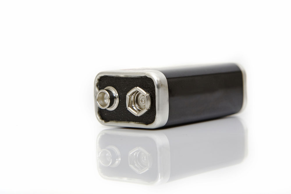
(A 9V battery powers the taser circuit)
The circuit relies on a 9V battery to deliver power to each electrical component, including several transformers, oscillators, and capacitors. A two-stage conversion process occurs, allowing the circuitry to function. First, the step-up transformer boosts the battery’s kV input voltage. In turn, this provides power to the oscillator, which generates sporadic AC waveforms. From there, that current charges the capacitor. Another transformer receives power after a battery voltage increase of 10-50kV at a rate of 5-40Hz occurs. After this happens, the stored electricity gets sent to the two conducting metal plates.
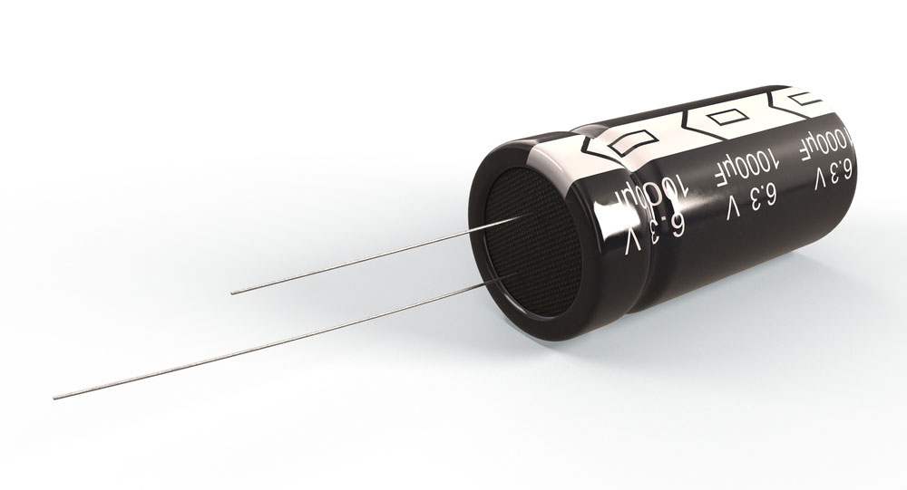
(Current charges the capacitor before it transmits to the circuit’s receiving end)
The two conducting metal plates at the circuit’s output contain a space in-between. Because of their specific positioning, the plates hold a high voltage. When you press the stun gun against a target, the electrical pulses jump from one plate to another. As a result, the electricity flows directly into the human body’s nervous system, weakening the muscles. However, a 3mA voltage will not inflict damage.
Taser circuits support two settings: probe mode and drive stun mode. While drive stun mode stops the target, probe mode fires two probes at a subject. Both methods pass electricity into the target.
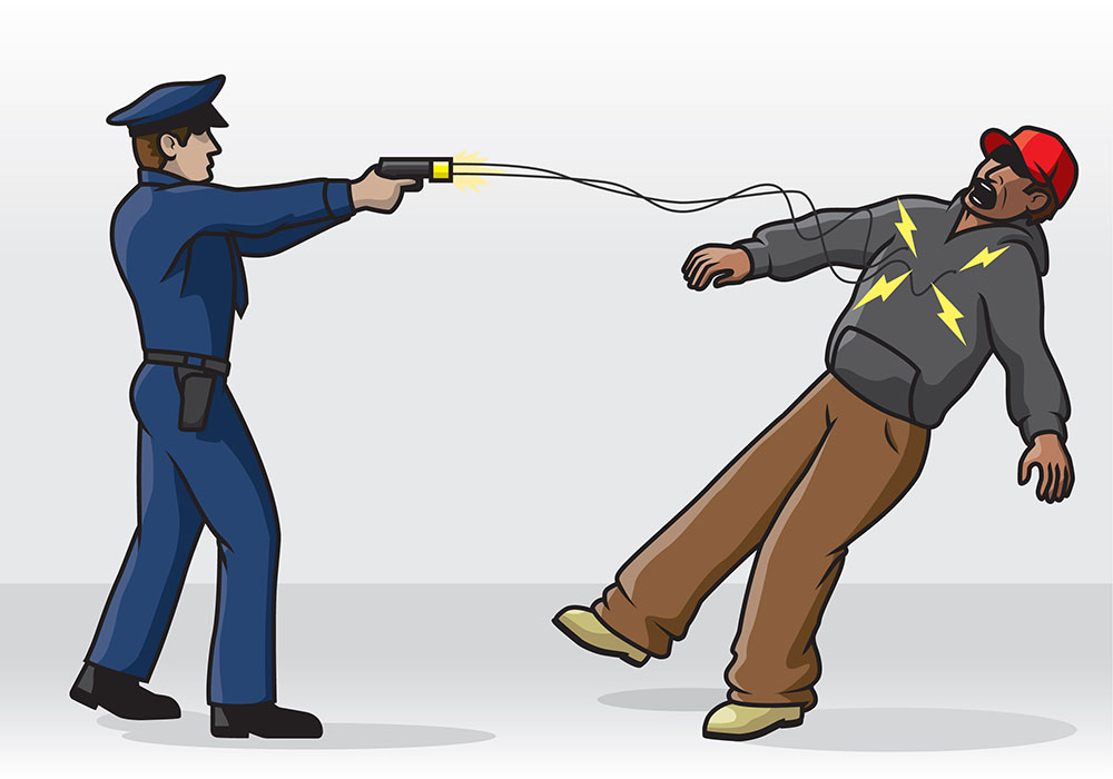
(A stun gun with probe mode)

4. How to Develop a Taser Circuit
This guide explains how to build a DIY stun gun circuit.
Selection of Components
For this circuit, we outlined the transformer and battery specifications. Additionally, we covered the transformer and the spark gap build process.
Transformer Specifications
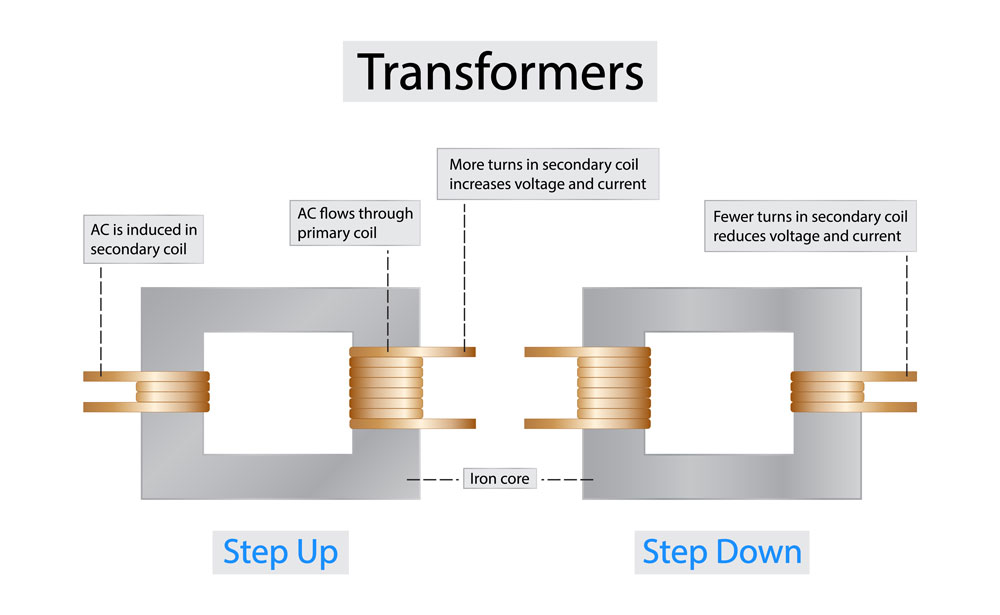
(A transformer for the circuit)
The EE-core-based transformer’s center column, with a 0.5mm air gap, contains a 20-25mm2 cross-section. Both polarities’ configurations also differ. This transformer contains 2×12 turns of wire with a 0.4mm diameter on the primary polarity. Meanwhile, the secondary polarity consists of 700 turns of wire at 0.1mm.
Wounding the secondary polarity in several isolated layers prevents the wire enamel from snapping due to voltage exposure.
Battery Specifications
Usually, six 1.5V cells or seven 1.2V cells provide power to a taser gun. Ideally, Lithium-polymer, Lithium-ion, or two cells should connect in series. Additionally, this device could generate 1.5 amps when turned ON.
When the device switches to ON, it may generate a 1.5A current, which may cause traditional batteries to perform poorly and deplete rather quickly.
Transformer
To build a transformer, you will need the following components:
- 0.20mm or 0.125mm copper wire
- Ferrite rod
- 0.25mm LDPE sheets
First, apply an LDPE coating on the ferrite rod. Next, set the winding to 200-250 on the IDP. If the ferrite rod measures more than 1’, you can set more winding. You will also need to apply another LDPE coating and set another 200-250 winding. Doing so leads to 5-6 tiers, equivalent to 1000-1400 turns. Also, stay cautious when following these steps to prevent any damage in the process. The transformer also sends back a feedback voltage to the winding.
Next, repeat the insulation process and configure the main winding to 15-20 turns at 1mm of wire. Too much winding generates a weaker currency and a reduced T2 secondary spike. In addition to that, we suggest deploying MKP capacitors because they contain very little ESR and ESL.
Spark Gap
The spark gap, which behaves like a voltage regulator, contains two crossed wires with a 1mm spacing. It electrifies when the output voltage can ionize the air between the wires. Placing this inside a small plastic box with organic mineral oil prevents bubbles from forming. So implementing this approach keeps issues from arising.
Circuit diagram and circuit design
(A 555 IC timer)
Overall, the circuit utilizes a 555 IC timer, which connects in an astable mode. It generates rectangular waveforms with a duty cycle and variable frequency. Meanwhile, an IRF840 MOSFET obtains the signal. You can also integrate a bipolar transistor instead of the MOSFET. If you deploy this method, place a 100 Ohms resistor between the transistor’s base and the 555 IC timer.
A BU406 BJT performs well, but a smaller BJT can also work. It should continually handle 2A of power. An inductive boost snubber seems impractical because the circuit runs on a weaker electric current. Additionally, the device runs on a battery, which means the power cannot distribute through a resistor.
A snubber will also reduce the number of firing levels on the circuit. Ensure you incorporate a push-button switch since it can ultimately serve as a safeguard.
Calculating and Ordering Samples online

(Online services offer a PCB manufacturing process)
EasyEDA provides easy-to-design online circuit board services for your needs. Select the PCB fabrication file from the file menu when you finish the PCB’s design. Next, a PCB order page will load, providing you with the downloadable PCB Gerber files. You can then deliver the files to a PCB manufacturer of your choosing. WellPCB offers a wide array of options. For example, you can choose the number of circuit boards to order and the number of layers needed. Additionally, it presents choices such as copper weight, PCB color, and PCB thickness.
Proceed to the add to cart link when you finish making your selections. From here, you can finish your order, which arrives a few days after submitting the order.
Test

(A multimeter tests the battery)
For this test, a multimeter will provide you with an accurate reading. First, insert the battery into the terminal and set the multimeter to AC. Doing so allows you to test the transformer’s output voltage. To display the correct reading, configure it to a high voltage first, then change it to a low voltage. An overloaded multimeter may provide inaccuracies.
5. Taser Circuit Applications

(A taser circuit provides the owner with protection)
Stun guns equipped with a taser circuit can provide varying levels of protection. A police officer and security guard utilize it to protect humans from an attacker or animal. Lastly, it can serve as a weapon during a war.
6. Limitations of Taser Circuit

(Apply caution when working with a taser circuit)
However, some limits still exist. For example, the circuit must generate a high-voltage pulse, making it dangerous. So it would be best to remain cautious while integrating it into the device. Corona discharge and stray capacitance will need special consi eration. Otherwise, they could impact the device output voltage.
Touching any part of the output without wearing protection will cause the voltage to transmit an electric shock throughout the body. As a result, this will impact the nervous system, leading to temporary paralysis or weakness. People suffering from cardiac issues should avoid working with these circuits. That’s because it may lead to cardiac arrest.
Conclusion:
A taser circuit, implemented in stun guns, can stop or prevent an immediate threat from an attacker exhibiting erratic behavior. When that happens, the circuitry produces a high voltage that will stun the target’s nervous system. Three types exist on the market today, which provide different levels of effectiveness while containing varying electrical components. Additionally, remain extremely cautious when working with this circuit. Otherwise, you will end up feeling the shock wave’s full impact.
Feel free to contact us with questions regarding a taser circuit!


