
Does your application involve generating sound, and do you need more information on how to get this done? Or do you want to know more about a device that can generate sounds? Luckily, we have the answer. The tone generator circuit is all you need.
Although tone generator circuits work in different applications and sometimes use different technologies to operate—the working principle is still the same.
So, in this article, we will tell you the secret behind how a tone generator circuit works, how to create an easy tone generator circuit and its different applications.
Buckle up and let’s dive in!
Contents
How Does a Tone Generator Circuit Work?
Also referred to as an audio signal generator, the tone generator is a device that generates artificial sound frequencies. It utilizes electrical signals and transforms them into audible sounds.
But that’s not all.
The tone generator can create different sounds. However, this depends on what the application needs.
For example, in an alarm circuit, the tone generator would generate sound loud enough to wake up any person.

Alarm Clock
Musical instruments, on the other hand, create simpler sounds—depending on the musical scale’s frequency.
Simply put, the tone generator is capable of generating various sounds required by different applications.
Now, how a tone generator circuit works largely depends on the application type.
For instance, a tone generator circuit in a traditional Hammond organ will make electric signals by allowing current to flow through its vacuum tubes. This process results in the current’s oscillation.
The oscillated current is then altered by organized mechanical elements that ensure the signals are proportional.
How Does a Tone Generator Work in a Modern Tester?
In modern testers, a modified DC is what supplies the electronic signal to the tone generator circuit. Plus, integrated circuits are responsible for modifying the DC.
Here’s the best part.
Even computers and mobile devices can generate output tones. However, these devices use digital representations of these sounds to create these tone signals.

Mobile Devices
Furthermore, these electrical signals are what tone generators transform into audible waves.
What’s interesting about this process is; it’s similar to how home stereo systems create audio waves.
The electronic signals move through a coil that creates a magnetic field when charged with current. Additionally, you can find the coil of a tone generator circuit near a magnet. There’s also a connection between the coil and a paper or plastic flexible membrane.
So, when the coil receives the generated electronic signal, it rapidly charges the magnetic field. This rapid charging forces the magnetic field to either repel or attract the permanent magnet.
For this reason, the connected membrane vibrates fast and generates the compression waves we know as sounds.

How Do You Make a Tone Generator?
Now that you understand the secret behind how a tone generator circuit works, let’s look at how to build a simple tone generator circuit using a 555 timer IC.
Additionally, there are different variations of tone generator circuits, including the sawtooth, triangle, sine, and square wave generators. These periodic signals are capable of creating different sounds when connected to an audio transducer.
So, we’ll be learning how to make a square wave generator circuit that produces constant square wave output. Also, the oscillation frequency of this circuit ranges from 670 to 680 Hz.
Here’s the circuit diagram:
Hardware Components
Here are the components you need to build this circuit:
- Breadboard (1)
- Quarter-watt variable resistors (1k ohm and 150 ohms) (2)
- Capacitors (0.1 uF and 0.01 uF) (2)
- Battery holder (1)
- 9-volt battery (1)
- NE555 timer IC (1)
- Speaker (8 ohms) (1)
- Test lead (alligator-clip) (1)
- Potentiometer (100k ohm) (1)
- Gauge insulated hookup wire (22)
- Soldering iron (not less than 40 watts) (1)
- Solder (lead-free variety preferred)
- Portable wire cutters (1)
- Plier (Needle nosed) (1)
- Wire strippers (1)
Steps
Here are the steps to follow for building this circuit:
Step 1: Set Your 555 Timer Chip
First of all, identify the pins of your NE555 timer IC. If you’re having trouble identifying the pins, first find pin one, which sits at the left uppermost corner of the chip. Plus, it becomes easy to identify the other pins—once you’ve found pin one.
Also, if you’re having difficulties installing your 555 timer, it could be a fault of the pins. So, check if they are right-angled. If the pins are not right-angled, straighten the pins so they fit into the holes of the breadboard.
Luckily, you can do this by pressing down the side of the chip on a flat surface. But, don’t apply too much pressure otherwise you’d damage the chip.
Step 2: Install the 555 Timer Chip to the Breadboard
Next, place the NE555 timer IC properly on your breadboard. Also, ensure that pin 1 is in the right position (lower left position).
After placing the 555 timers on the board, make sure the pins go through the board and solder them to make connections. If the pins don’t fit properly, don’t force it, rather refer to step one.
Step 3: Wiring
Now, take the length of your hook-up wire and create a connection between pins six and two. Then solder it. Take another length of your hook-up wire and solder it to pins four and eight.
Next, set your 1k-ohm variable resistor (like the picture below) and install it on the right side of the 555 timer. Also, solder the second lead of the resistor to pin seven. Then, solder the other resistor to pin eight.
Take your 0.1 uF capacitor and install it on the left side of the 555 timers. Next, solder the first capacitor lead to pin one and solder the other capacitor lead to pin two.
Take the other 0.01 uF capacitor and install it next to the resistor. Now, solder one capacitor lead to pin five and then use a length of hook-up wire to create a connection between the capacitor lead and pin one.
Finally, install the resistor (150 ohms) and solder one lead to pin four to complete the wiring process. Everything should look like this:
Step 4: Install Your Loudspeaker
Cut two 3-inch pieces of hook-up wires and connect one to pin three and the other to the free lead of the resistor (150 ohms). These hook-up wires will serve as your speaker leads.
Next, connect your speaker leads to the speaker and cut the alligator-clip head into two. Also, strip the ends of the wires and solder them to pin six and seven.
Take the red wire of your battery clip and solder it to pin eight and solder the black wire to pin one.
Step 5: Test Your Circuit
Test your circuit with the potentiometer to see if it works. So, when you connect the 9v battery, a tone should ring out from the speaker; if it doesn’t try checking your connections and try again.
Applications
You can use tone generator circuits in the following applications:
- Used in toys and doorbells to generate melodic sounds
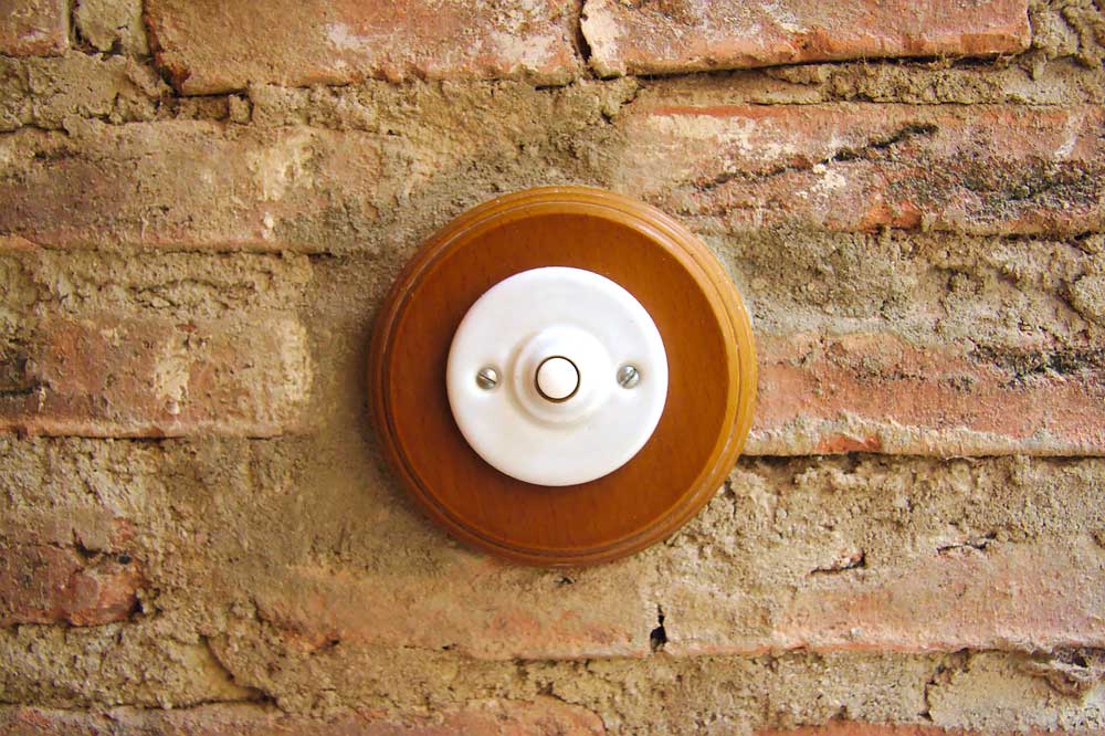
Doorbell
- Works in home security systems like burglar alarms
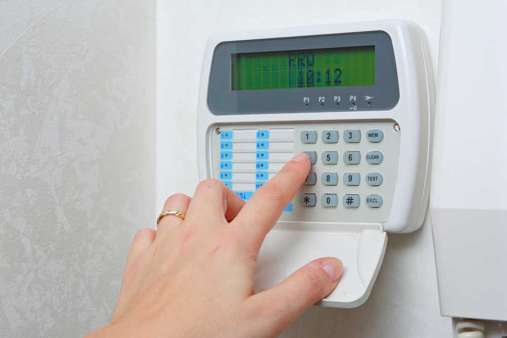
Burglar Alarm
- Also works in telephone applications to produce dial tones
Final Words
Tone generators are extremely versatile circuits.
You can use them to test audio frequency equipment, create audio pulses, and even create sound in modern devices like mobile phones.
In addition to their versatility, tone generators work differently for different applications.
Some types of tone generators include the 2 melody generator electronic circuits, ding-dong sound generator, two-transistor siren generator, and many more.
That wraps it up. Since we value your opinions, feel free to reach us if you have any questions or suggestions. We’d love to hear from you.


