
When it comes to tactile sensors, touch switch circuits are among the simplest ones. Despite their simplicity, these amazing pieces of technology are everywhere. Touch screens, for instance, are just arrays of touch switches on top of a display. They have other vast applications, including wall switches, lamps, and even public computer terminals.
This article will give you all the info you need about touch switch circuits. That will be all you need to add modern touch facilities to your electrical or electronic devices.

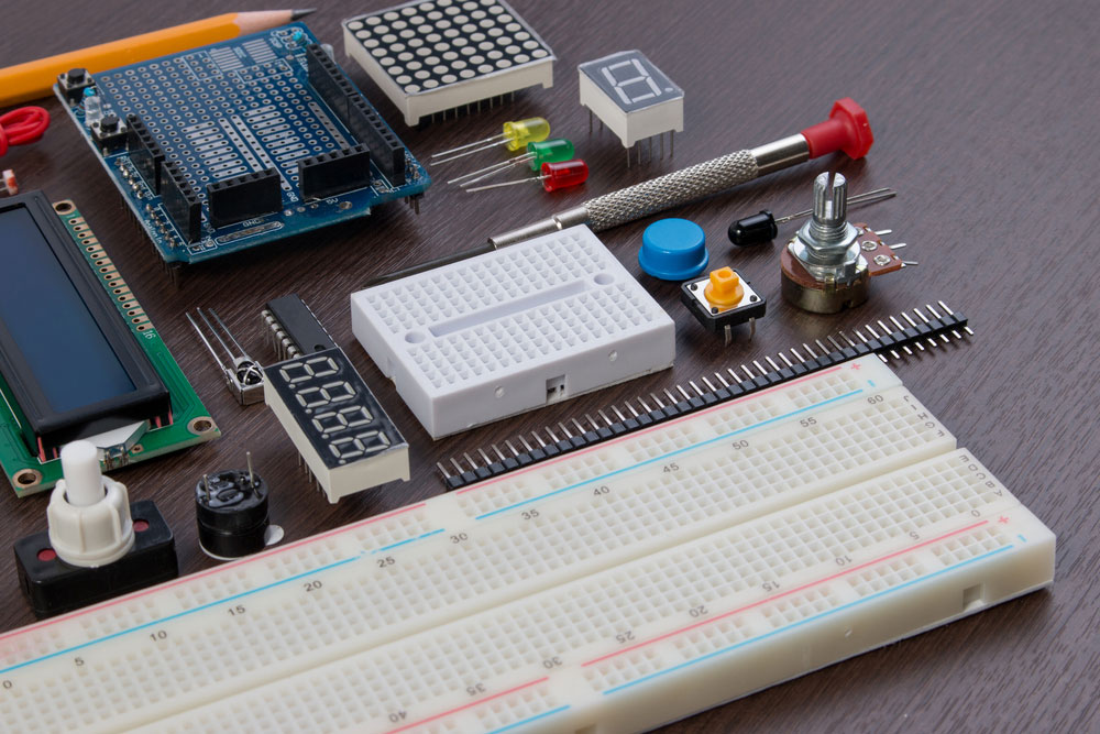
Touch Circuit Illustration
Contents
- 1 How Does a Touch Switch Circuit Work?
- 2 7 Different Touch Switch Circuits
- 2.1 1. A simple touch on and off switch circuit
- 2.2 2. Touch switch circuit using 555 timer
- 2.3 3. Touch toggle switch circuit using NAND gate
- 2.4 4. Touch activated Switch circuit
- 2.5 5. Simple touch switch using transistor
- 2.6 6. Touch plate switch circuit using UJT
- 2.7 7. Touch Motor Controller circuit using SCR and Schmitt Trigger
- 3 How to Make a Simple Touch Switch Circuit
- 4 Conclusion
How Does a Touch Switch Circuit Work?
Touch switch circuits are essentially just normal switches, albeit with special sensors. In this case, when the sensors pick up some change in stimuli from direct contact, they react by closing a switch. It, in turn, allows the current to flow. The kind of sensor used will often be what determines the inner workings of the switch. Touch sensors that make up modern types of touch switches fall under the following categories:
- Capacitive touch switches. These use the human body’s capacitance to trigger current flow, which controls the opening and closing of the switch.
- Resistive touch switches. – This type relies on pressure from touch to lower the resistance between two electro-conductive surfaces.
- Piezo touch switches. – These are less common in many modern applications as they work on the principle of mechanical binding of piezo ceramic. They work for both insulating and conducting materials but are more costly to produce.
7 Different Touch Switch Circuits
There are many kinds of touch switches, and each acts as an important electronic component in the devices that utilize them. The common types include:
1. A simple touch on and off switch circuit
For this circuit, you will need only a single MOSFET and a single relay. They work using electric power that is from as little as a 9V DC supply voltage to the circuit. Its working principle is that when you touch the Ground and Gate terminals, the appliance is in the OFF state. When the Gate and the Supply connect due to touch, the Switch is in the ON state.

Touch Switch
2. Touch switch circuit using 555 timer
This rather simple ON and OFF touch switch circuit has a lot in common with the voltage 2 group. The key differentiating factor is the integrated circuit timers included. These could be NE555 or LM555. The touch switch circuit, in this case, has two touchpads, one for each state. It works by utilizing the high input impedance of the trigger pin of the 555 IC. The induced voltage of the human body then rises for a time determined by C1 and R1. After that, the transistor drives the relay, which then drives the load.
3. Touch toggle switch circuit using NAND gate
Here, a digital 4011 logic gate forms the base of the touch switch circuit. The second pin on the IC is “HI” logic. Touching the plate connected to the second pin results in a HIGH logic. When there is no touch to the plater, there is LOW logic. The inclusion of the 22-ohm resistor on pin 1 results in the circuit being susceptible to touch.
4. Touch activated Switch circuit
This type is often part of integrated digital circuits. It uses a single metal plate and works like a typical ON and OFF switch. The switch circuit utilizes an IC to take electrical signals from the finger. That is what becomes the digital signal which triggers a change of the OFF or ON states.
5. Simple touch switch using transistor
It is an updated version of the original simple ON and OFF touch switch circuit. It is often a replacement of the original when the IC controlling the switch operations proves to be cumbersome. The simple touch switch uses just a transistor. The A and B contacts connect when the switch needs to relay. This relay releases when the B and C contacts receive stimuli from touch.
6. Touch plate switch circuit using UJT
As its name suggests, it uses the UJT 2N3819 as the main switching component. It is beneficial when the switch is part of devices that are not always near electric lines. By touching metal 1 and 2, the switch turns ON. Touching metal 2 and 3 triggers the relay resulting in an OFF state.
7. Touch Motor Controller circuit using SCR and Schmitt Trigger
Compared to the other types, this one is quite complex. Touching the metal plate in the circuit causes the Schmitt Trigger Circuit to take a signal from the Oscillator Circuit. It also pushes a bias current to the base of Q1-2N5088. That triggers an SCR1 which drives the 12V motor.

How to Make a Simple Touch Switch Circuit
Building a touch switch circuit is not nearly as complicated as it used to be in the past. These days, basic electronic components can be used in place of sophisticated touch switches and expensive microcontrollers. It means that with components like transistors and resistors, you can build a simple touch switch circuit.
Project Components
To begin with, the components that you will need for this project include:
- A breadboard or our Printed Circuit Board (PCB).
- A 9-volt power source
- Connecting wires
- 2 Hard Copper Wires or Metal Strips
- A BC547 NPN Transistor
- 5mm LED
- A 270-ohm resistor
- 100k ohm resistor
To build the circuit, the steps that you need to follow are as follows:
1: Connect the BC547 transistors on the breadboard or the PCB.
2: Using a jumper wire, connect the Base Pin of the first transistor to the Emitter Pin of your second transistor.
3: Connect the 100K ohm resistor between the Collector Pin of the second transistor and the VCC pin.
4: Connect the 270-ohm resistor and LED to the Collector Pin of the first transistor.
5: Using another jumper wire, connect the Emitter Pin of the first transistor to GND.
6: Connect metal strips between the 100K ohm resistor and at the Base Pin of the second transistor.
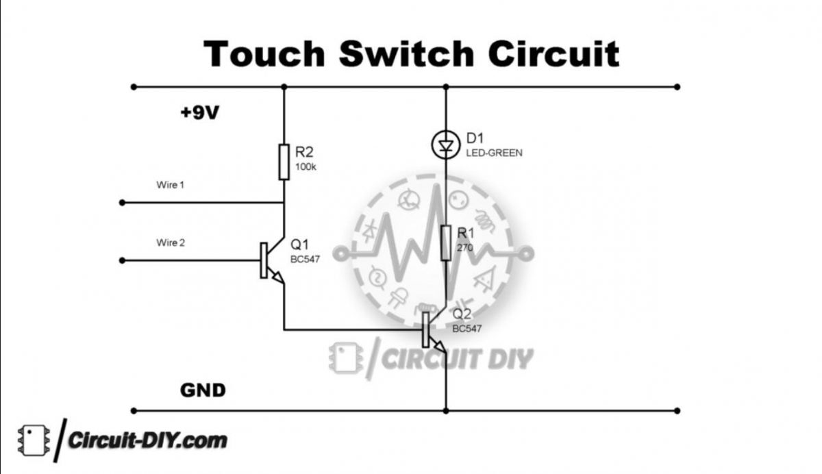
Simple touch switch circuit
Once you have completed all these steps, you can proceed to see if the circuit is working. Touch the metal strips connected to the circuit to test if it is working as intended. This simple switch can have a wide range of applications. For instance, you can use it to detect stray voltages or electrostatic build-up. Another common use case is in dusty or wet areas where typical switches would not be suitable.
Conclusion
Touch switch circuits are beneficial. Thankfully, incorporating them into modern electronic design has never been easier. They are easy to build, especially with the right components. You can check us out for some of the best components. That is all you need to get started on your do-it-yourself (DIY) project that makes use of a touch switch.


