Contents
What Is A Transformerless Inverter?
A power inverter converts lower-voltage direct current (DC) electricity to higher-voltage alternate current (AC) electricity, which appliances use.
Rather than needing an internal transformer to convert energy, a transformerless inverter can increase voltage using a computerized multi-step process. The electronic components within the inverter change lower-frequency DC power to higher-frequency AC. Then, it converts the power back to DC and finally to standard-frequency AC voltage.
3 Best Circuits For Transformerless Inverters
The three best circuit configurations for transformerless inverters are the IC 4047, a 200-watt compact design, and solar inverter circuits. They are small, relatively simple, and rely on battery or solar power rather than an internal transformer.
IC 4047
Fig 4: IC 4047
The IC 4047 is one of the simplest circuits you can use for a transformerless inverter. It doesn’t require bootstrapping or special driver ICs.
However, it’s two to three times larger than similar N-channel devices with decreased thermal tolerance and increased current specifications. Thus, designers avoid it for professional and commercial units.
How It Works
The IC 4047 is a low-power multi-vibrator that you can use in both astable and monostable MV modes. You can integrate external triggering inputs in astable mode (true gating or complement gating). In monostable mode, you can use a positive edge trigger or a negative edge trigger for the IC.
Its re-triggerable feature allows you to extend output timing to the amount you need.
It also has a built-in oscillator that allows variable frequency options with an external RC network.
Configuration
- Power: Batteries rated for 190V when fully charged and 160V when moderately charged
- IC 555: PWM
- Opamp IC: configured like a comparator with triangle waves to process the required SPWMs
- BJTs buffer switch: set according to SPWM pulses with low-side MOSFETs switched to the same pattern
- MOSFETs: should be rated for handling 3kva transformerless inverter (such as IRFB4137PBF-ND)
- Ferrite core: instead of a heavy iron transformer
Frequency Testing
Use the following formula, measuring f in Hz, Rt in Ohms, and Ct in Farads:
f = 1/1.453 x Rt x Ct
You’ll want to test the frequency range output with a digital frequency meter until you get the desired results.
Parts List
- C1 = 0.1uF / PPC
- R1 = 56k
- IC pin 10 /11 resistor = 330 ohms – 2nos
- Upper P-channel MOSFETs = FQP4P40 – 2nos
- Lower N-Channel MOSFETs = IRF740 = 2nos
- MOSFET gate resistors = 100k – 2nos
- Opto-couplers = 4N25 – 2 nos
- Zener diodes = 12V, 1/2 watt – 2 nos
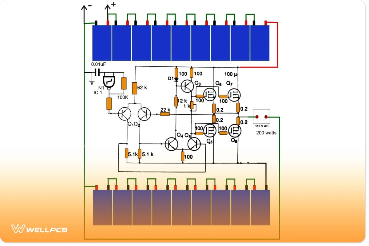
200-Watt Compact Design
The 200-watt configuration is simple and efficient, requiring no heavy transformer. The batteries that power it don’t take up much space and output 110 V AC at 200 watts. Quality power supply assembly techniques ensure compact, efficient integration of the battery system with the inverter circuitry.
How It Works
The 200-watt simple inverter circuit uses high-voltage DC input voltage from eighteen 12-volt batteries. The IC needs a strict operating voltage of 5-15 volts, so that comes from one of the 12 volt batteries.
Configuration
- Power: eighteen 12-volt batteries in series
- Oscillator: gate N1 (from the IC 4093)
- IC: input from one of the 12-volt batteries, applied to relevant IC out
- For true sine wave inversion, use a sine wave generator instead of an input oscillator
Parts List
- Battery = 12V/4AH, 18 nos.
- D1 = 1N4148
- NAND IC = 4093,
- Q1, Q2 = MPSA92
- Q3 = MJE350
- Q4, Q5 = MJE340
- Q6, Q7 = K1058,
- Q8, Q9 = J162
Transformerless Solar Inverter Circuit
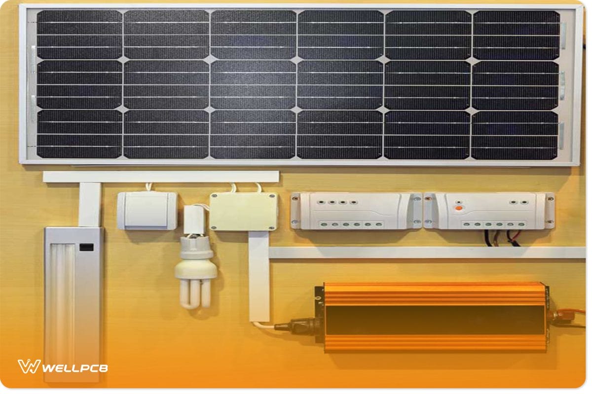
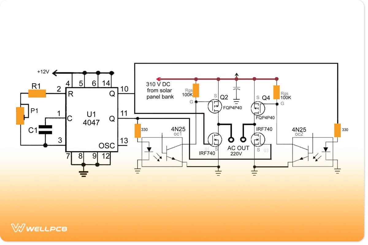
Fig 3: Transformerless Solar Inverter Circuit System
A transformerless solar inverter circuit design eliminates a transformer by using high-voltage MOSFETs to harness solar energy. A voltage regulator can help regulate power fluctuations based on power loss and gain from sunlight fluctuations.
How It Works
Transformerless solar inverter circuits convert solar energy into AC electricity. They have three main stages: the oscillator, output, and power delivery stages.
Configuration
- Power: solar panels with an open circuit voltage range of 17V (dusk) to 24V (bright sunlight), fed into B1 and B2
- Dropping resistor and zener diode: limit to 15V zener voltage
- Voltage stabilizer: to regulate solar output voltage between sunny and cloudy days, which could range from 170V-260V
- Mosfets: N and P types rated at 450V and 5 amps
- Oscillator: IC 555
- Output: high-voltage power MOSFETs
Formulas for R1, R2, and C1
T1=0.7(R1+R2)C and T2=0.7R1C
so
T=0.7(R1+2R2)C or f=1.4/(R1+2R2)C
where
T1 = high period, T2 = low period, T = total period, and f = frequency
Parts List
- B1 and B2 = from solar panel
- C1 = 0.1uF
- Diodes = are 1N4148
- R1 = 6K8
- R2 = 140K
- R3 = 10K, 10 watts,
- R4, R5 = 100 Ohms, 1/4 watt
- Z1 = 5.1V 1 watt
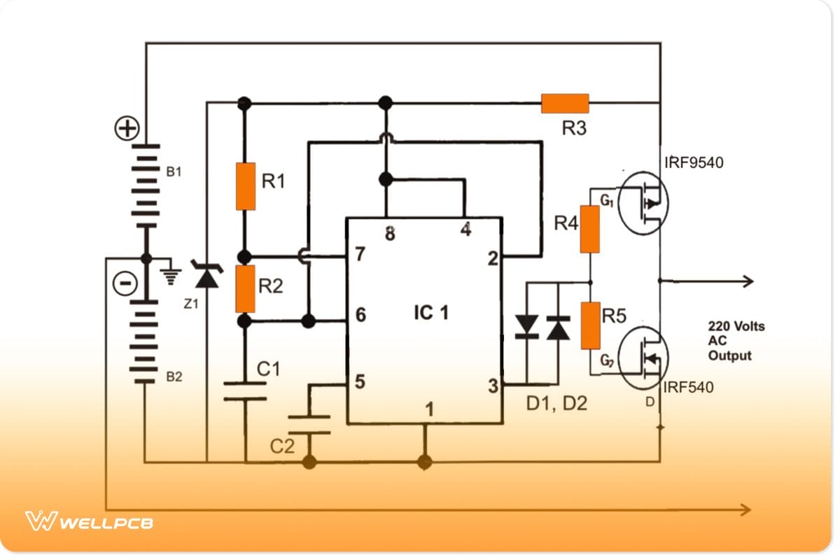
Fig 5: Transformerless Solar Inverter Circuit System
Alternatively, you can install a complete H-bridge inverter circuit. The advantage of this is that you’ll only need to install a single solar panel arrangement to have 220V output.
A transformerless solar inverter circuit design eliminates a transformer by using high-voltage MOSFETs to harness solar energy. A voltage regulator can help regulate power fluctuations based on power loss and gain from sunlight fluctuations.
Configuration
- Power: solar panels with an open circuit voltage range of 17V (dusk) to 24V (bright sunlight), fed into B1 and B2
- Dropping resistor and zener diode: limit to 15V zener voltage
- Voltage stabilizer: to regulate solar output voltage between sunny and cloudy days, which could range from 170V-260V
- Mosfets: N and P types rated at 450V and 5 amps
- Oscillator: IC 555
- Output: high-voltage power MOSFETs
Formulas for R1, R2, and C1
T1=0.7(R1+R2)C and T2=0.7R1C
so
T=0.7(R1+2R2)C or f=1.4/(R1+2R2)C
where
T1 = high period, T2 = low period, T = total period, and f = frequency
Parts List
- B1 and B2 = from solar panel
- C1 = 0.1uF
- Diodes = are 1N4148
- R1 = 6K8
- R2 = 140K
- R3 = 10K, 10 watts,
- R4, R5 = 100 Ohms, 1/4 watt
- Z1 = 5.1V 1 watt
Alternatively, you can install a complete H-bridge inverter circuit. The advantage is that you’ll only need to install a single solar panel arrangement to have 220V output.
Installation Considerations of Transformerless Inverters

Fig 4: Workers who install and test transformerless inverters
Using traditional inverters means each must pair with a single or custom-isolating transformer. The power immediately reduces since isolated transformers are at most 99% efficient. Plus, the bulky size and range limit immediately get in your way. Transformerless inverters tied directly to the building or the sub panel if it is sufficient size.
Without the heavy transformer, the design is lightweight and maneuverable, making installation options increase. I would also eliminate the massive amounts of DC wiring and the length and cost of AC wiring. You can connect multiple parallel inverters without transformers, utilizing direct power for the most stable performance.
Differences Between Transformer-Based and Transformerless Inverters
The major difference between transformerless inverters and traditional inverters is the transformer itself. The absence of a transformer frees up the space for a cleaner, more lightweight, and direct design. It also makes it more efficient. The computerized process and upgraded electrical components substitute for a transformer.
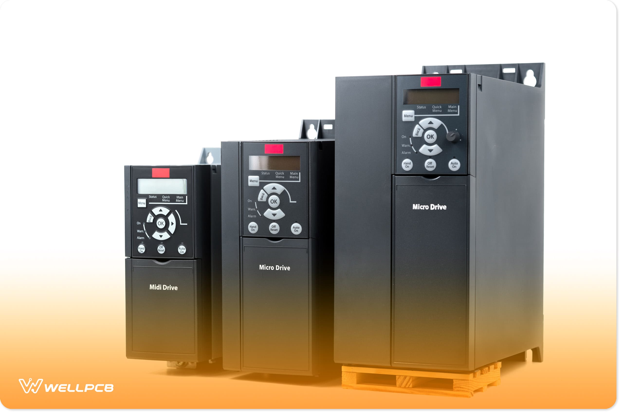
These uninterruptible power supplies are now common in data center environments with smaller installations. They are available in a range of power ratings from below 10 kVA to around 300 kVA.
Benefits Of Using A Transformerless Inverter
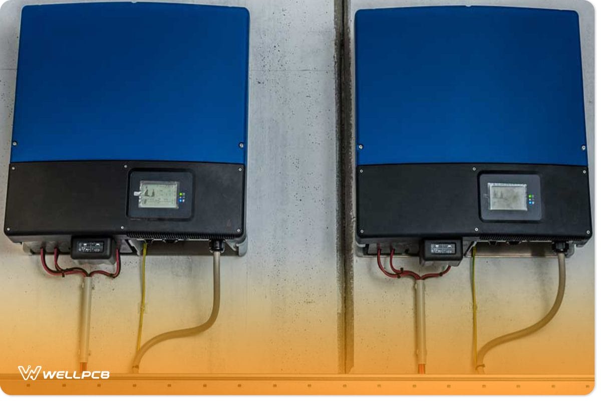
Fig 5: Lightweight and compact transformerless inverter
Transformerless inverters are more efficient than conventional ones and able to avoid internal energy loss. It also eliminates extra component costs due to the absence of a transformer, which is bulky and large. The transformerless versions are light and compact and use electronic switching rather than mechanical.
Transformerless inverters also have less mechanical noise and less heat from mechanical components. Overall, these properties make the build cheaper due to not needing cooling fans, transformers, and other bulky components.
The conventional inverters work via a single PowerPoint. Meaning, performance for one component that is low will lower the overall DC output. With transformerless inverters, you can install them in two different directions while generating DC output.
Conclusion
Overall, transformerless inverters are cost-effective because of the fewer and more efficient electrical components. You have different options to choose from with circuits, but the overall advantage of transformerless models is versatility. The use of smaller, more compact appliances and electronics makes for cheaper production and cost for the consumer.
The circuit options depend on what kind of DC output is required. Alternatively, the transformerless components give the advantage of speed and efficiency. This technology has been developing and improving for decades and will revolutionize electronic consumption in the future.